Homebrew / Open-Source · Volume 5
Homebrew & Open-Source Analog Computers — Volume 5 — Substrates and physical construction
Chassis, rails, backplanes, panels and jacks — including the recurring question of whether a modular synthesiser format can be turned into an analog computer
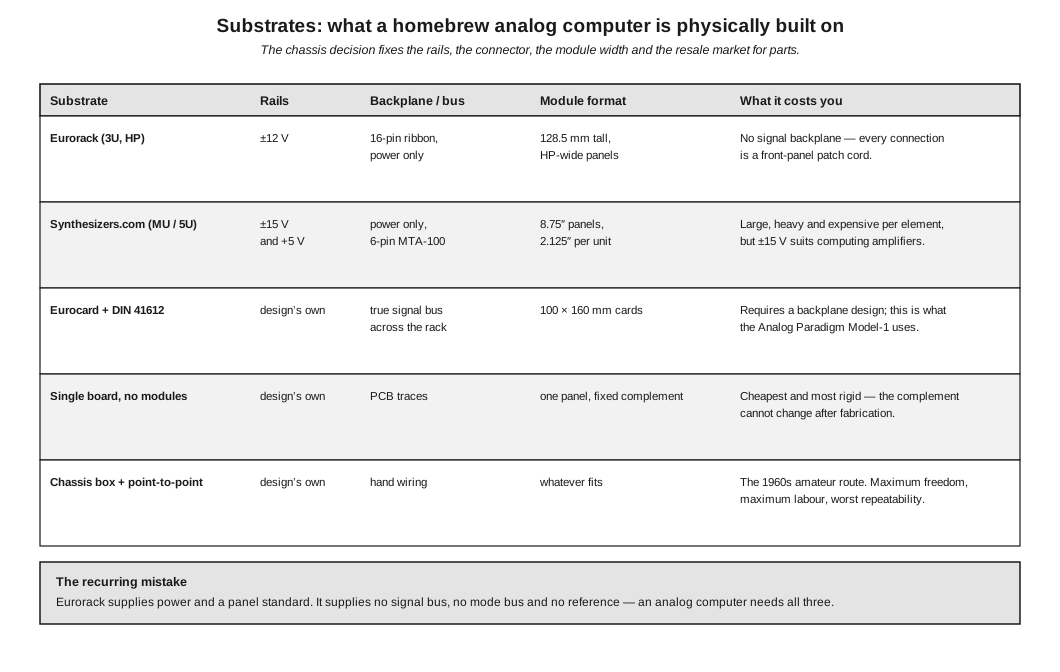
Figure 1 — The substrate decision and what each option fixes. Eurorack figures from the Doepfer A-100 documentation; Synthesizers.com figures from that manufacturer’s technical information; the Eurocard row describes the Analog Paradigm Model-1 arrangement. Diagram authored for this dive by build/make_diagrams.py.
5.1 About This Volume
The substrate is the first irreversible decision in a homebrew build and the one most often made by accident — a builder has a case, so the machine becomes whatever fits in it.
It deserves better, because the substrate fixes four things at once: the supply rails every computing amplifier will run on, the connector and therefore the expansion path, the module width and therefore the element density, and the second-hand market the builder can draw parts from. Changing any of them later means rebuilding.
This volume sets out the realistic options, then treats the two subjects that decide whether a machine is pleasant or miserable to use: the patch field, and the routing of the small number of nodes that are genuinely sensitive.
It also answers a question that recurs whenever someone with a modular synthesiser discovers analog computing. The answer is more interesting than either “yes” or “no”.
Cross-references: Vol 2 §4 and Vol 3 §4 for why the summing junction and the integrating capacitor need careful treatment; Vol 4 for what each documented design chose.
5.2 What the Substrate Fixes
Table 1 — What the Substrate Fixes
| Decision | Consequence |
|---|---|
| Rails | Sets the maximum machine unit. A ±12 V format cannot run a ±10 V machine with much headroom; a ±15 V format can |
| Backplane | Determines whether mode control, reference and ground are distributed behind the panel or have to be patched on the front |
| Module format | Sets how many elements fit in a given width, and therefore how big the machine has to be to hold twenty amplifiers |
| Connector | Determines whether modules are interchangeable and whether a later module can be added without rework |
| Parts ecosystem | Whether cases, power supplies, panels and blanks can be bought or must be made |
The second row is the one that separates an analog computer from a collection of analog circuits, and §6 returns to it.
5.3 Eurorack
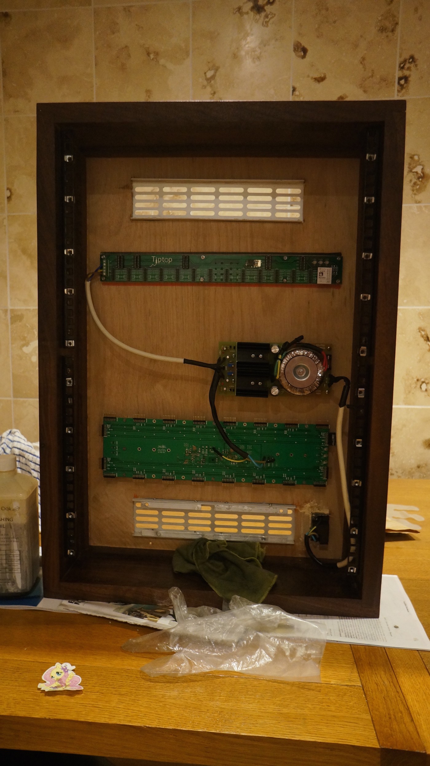
Figure 2 — A Eurorack chassis before any modules are fitted: mounting rails, two bus boards and a linear supply. This is the entirety of what the format provides — power distribution and a mechanical standard. Photograph: File:C-g.’s modular synthesizer - The eurorack PSU is in (2014-12-01 20.42.27 by c-g.).jpg by c-g., CC BY 2.0, via Wikimedia Commons.
5.3.1 What the Format Specifies
From the Doepfer A-100 documentation, which defines the format:
Table 2 — From the Doepfer A-100 documentation, which defines the format
| Parameter | Specification |
|---|---|
| Panel height | 128.5 mm for all A-100 front panels (3U) |
| Horizontal pitch | 1 HP = 5.08 mm, that is 1/5 inch; actual panel widths are slightly under the calculated value for assembly tolerance |
| Rails | +12 V and −12 V on all versions; +5 V additionally on the A-100PSU3 |
| Bus connector | 16-way ribbon as standard, some modules using a 10-way cable; the 10-way carries −12 V, ground and +12 V, the 16-way adding +5 V, CV and Gate |
| Orientation | The coloured stripe on the ribbon marks −12 V and aligns to the bottom of the bus board |
Doepfer’s own warning is worth repeating because it applies with extra force to a mixed rack: applying other voltages or reversing polarity “will result in the module’s instant destruction”.
5.3.2 What It Gives a Computer Builder
A great deal, practically. Cases, rails, power supplies, bus boards, blank panels, knobs and jacks are all commodity items. Panels can be ordered cheaply in HP multiples. The element density is good: a summer or inverter fits comfortably in 4 HP, so a 84 HP row holds a useful complement.
5.3.3 What It Withholds
Three things, and they are exactly the three an analog computer needs.
There is no signal backplane. The bus carries power, and on the 16-way version a CV and a Gate line intended for a keyboard, not a computing bus. Every connection between computing elements is therefore a front-panel patch cord. On a synthesiser that is the point; on an analog computer it means the patch field is doing work the backplane should be doing, and the cord count for a modest program becomes large.
There is no mode bus. Vol 3 §2.1 established that IC/OP/HLT must reach every integrator simultaneously. Eurorack provides no line for it. A builder must either run a private bus behind the panels — at which point the format’s interchangeability is partly abandoned — or distribute mode control through patch cords on the front, which consumes jacks and invites a run starting with one integrator still in reset.
There is no reference. Nothing in the format defines a precision voltage, and the ±12 V rails are not one. A reference module must be built and distributed, again over the front panel or a private bus.
5.3.4 The ±12 V Problem
A ±10 V machine unit on ±12 V rails leaves 2 V of headroom. Vol 3 §6.1 argued that an analog computer must detect overload rather than silently clip, and detecting it requires the amplifier to have somewhere to go above the machine unit before it hits the rail. Two volts is thin, particularly with op-amps that do not swing to the rail.
The practical options are to adopt a ±5 V machine unit, which halves every signal and doubles the relative significance of every offset and noise term; to run the computing modules from a separate ±15 V supply and use the Eurorack case purely as mechanics; or to accept the headroom and instrument the overload detection carefully.
THE ANALOG THING is the informative data point here: it runs ±12 V rails with ±10 V machine units, which demonstrates the combination is workable in a carefully engineered design.
5.3.5 Can Synthesiser Modules Be Used Directly?
This is the recurring question, and the honest answer has three parts.
Structurally, the elements overlap more than expected. An attenuverter is a coefficient potentiometer with a sign. A DC-coupled mixer is a summer. A slope or function generator of the Serge dual-universal-slope-generator lineage is built around integrators and can genuinely integrate. A comparator module is a comparator. A ring modulator or VCA of the right type is a multiplier.
Electrically, three mismatches bite. Any module that is AC-coupled anywhere in its path is disqualified outright, because an analog computer is a DC machine and a coupling capacitor destroys the very integral being computed. Many modules are calibrated in volts-per-octave or in normalised CV ranges rather than in machine units, so their transfer functions are tuned for musical rather than arithmetic behaviour. And the accuracy specifications that matter here — offset, drift, linearity — are usually not published for synthesiser modules at all, because nobody buying one needs them.
Architecturally, the gaps in §3.3 remain. Even with a rack full of suitable modules, the machine still lacks a mode bus, a reference and a backplane, and those have to be added.
The defensible conclusion is that a Eurorack case is an excellent chassis for a purpose-built set of computing modules, and that a collection of synthesiser modules is not an analog computer and cannot be patched into one without adding the three missing subsystems. A builder who wants both should build computing modules to the Eurorack mechanical and power standard — which is a good decision — rather than expecting existing musical modules to serve.
5.4 Synthesizers.com and the 5U Formats
The larger American modular format is the better electrical fit and the worse practical one.
From the manufacturer’s technical information: power is +15 V, −15 V and +5 V, with the ±15 V reserved for analog circuitry and the +5 V for LEDs and digital circuitry specifically to reduce noise. Module height is 8.75 inches with a horizontal unit of 2.125 inches. Power reaches modules through a 6-pin MTA-100 connector, keyed by removing one pin and filling the corresponding hole so it cannot be inserted backwards.
Three observations follow. The ±15 V rails give a ±10 V machine unit five volts of headroom, which is comfortable and makes overload detection straightforward. The deliberate separation of digital and analog supplies is exactly the discipline Vol 4 §5.3 praised in Fitch’s separate 12 V relay rail. And the keyed power connector is a small thing that prevents a large class of destroyed modules.
The cost is size and money. At 2.125 inches per horizontal unit, a machine with twenty computing elements is a substantial piece of furniture, and per-element cost is high. For a builder who wants a modest, beautifully made machine and is not trying to reach twenty amplifiers, the format is attractive.
5.5 Eurocard and DIN 41612 — The Bussed Architecture
The one format in current use that was designed for this job is the industrial Eurocard, and the reference implementation is the Analog Paradigm Model-1.
Its arrangement, from the manufacturer’s module documentation: all computing modules are standard Eurocards, 160 × 100 mm, with two-row (A/C) DIN 41612 connectors. The minimum system is two 19-inch chassis, expandable to four, each holding a freely configurable complement.
The module set is worth setting out, because it is a clean statement of what a complete machine contains:
Table 3 — The module set is worth setting out, because it is a clean statement of what a complete machine contains
| Module | Contents |
|---|---|
| PS | Derives the “highly stabilized” ±10 V machine units; detects over- and under-voltage and overload |
| CU | The control unit — “the heart of the analog computer as it controls the overall operation”; three modes IC/OP/HLT, manual or repetitive, OP-time adjustable in 20 ms increments, external halt input |
| INT4 | Four integrators, each with four time constants (1, 10, 100, 1000), six inputs — three weighted 1 and three weighted 10 — plus initial condition and summing-junction access |
| SUM8 | Eight summers in two groups of four; four configurable as “free amplifiers” by disabling the internal feedback |
| PT8 | Eight precision potentiometers, one configurable as a free potentiometer with both ends accessible |
| MLT8 | Eight multipliers |
| MDS2 | Two elements switch-selectable as multiplier, divider or square-root circuit |
| CMP4 | Four comparators with electronic switches |
| XIR / XID / XIBNC | Resistor networks, diodes and Zener diodes, and BNC connections to external equipment |
Four features of this list are directly instructive for a homebrew builder, whatever substrate they choose.
The control unit is a module, not a switch. It is described as the heart of the machine. Vol 3 §2.1 reached the same conclusion from first principles.
The power supply is a computing module. It produces the machine unit and carries the overload detection, which puts both of Vol 3’s diagnostics in the one place every machine already has.
Integrators carry switchable time constants as standard, spanning three decades. This is the time-scaling facility of Vol 6 §6 built into the hardware rather than patched with different capacitors.
Summers can become free amplifiers. Disabling the internal feedback exposes a raw amplifier whose feedback the programmer supplies from the patch field — the cheapest possible route to arbitrary transfer functions, and the same idea as the free component bank in Fitch’s design.
The trade is that this architecture requires a backplane to be designed, fabricated and wired. There is no commodity analog-computer backplane to buy. For a builder intending more than about ten elements, designing one is nevertheless the correct decision, because the alternative is patching the mode bus by hand.
5.6 Single Board and Hand-Wired Chassis
The two remaining options bracket the others.
A single board — the Malmö thesis machine, Marbslab’s design, and in practice Fitch’s, whose computing core is one 150 × 99 mm board — is the cheapest and most rigid choice. Everything is on one PCB, the sensitive nodes are short, there is no connector to go intermittent, and the element complement is fixed at fabrication. For a machine of four to eight elements built to a known requirement, this is entirely correct and is what most modern homebrew designs do.
A hand-wired chassis is the 1960s route and PEAC’s modular units are its best example. It offers total freedom of layout and the worst repeatability. Fitch’s machine takes a hybrid position: a fabricated board inside a Pactec PT-10 enclosure with banana jacks on the panel for patching, which keeps the circuit repeatable while leaving the panel free-form.
5.7 The Patch Field

Figure 3 — Colour as the carrier of function, on a Telefunken RAT 7002 patch panel. Green, orange, white and yellow terminations group by role, with the element symbols and weights printed directly into the field between them. Photograph: File:Colorful Patch Panel, Telefunken RAT 7002 analog computer, Computer History Museum.jpg by Don DeBold, CC BY 2.0, via Wikimedia Commons.
5.7.1 Jack Size
Table 4 — Jack Size
| Size | Used by | Trade |
|---|---|---|
| 4 mm banana | Most commercial machines; Fitch’s build | Robust, stackable, cheap, universally available; large, so panel area limits element density |
| 2 mm | The Vogel design, danja/analog-computer | Compact enough for a dense field on a small panel; cords are less common and less robust |
| 3.5 mm jack | Eurorack-format builds | Commodity and compact; not stackable, so every junction needs a multiple |
Stackability deserves emphasis. Analog computer programs routinely take one output to three or four destinations, and a plug that accepts another plug in its back makes that a single action. Where the jack does not stack — the 3.5 mm case — the machine needs multiple/bus jacks provided as elements, and a builder who omits them will discover the gap on the first real program.
5.7.2 Colour
Every serious machine encodes function in colour, and the specific scheme matters much less than having one. Fitch’s panel artwork uses coloured rectangles to group each element’s jacks and distinguishes gain-1 from gain-10 inputs by colour, with the panel description document tabulating every colour against its label and function. That table is the machine’s reference manual, and its existence is a sign of a design intended for someone else to use.
5.7.3 The Panel Is the Documentation
The convention established in Vol 2 §8 applies with full force at the substrate level: print the element symbol, the input weights and the summing-junction location directly into the panel artwork. It cannot become out of date, it removes an entire category of patching error, and on a homebrew machine it costs nothing because the panel is being drawn anyway.
5.7.4 The Program Is the Patch
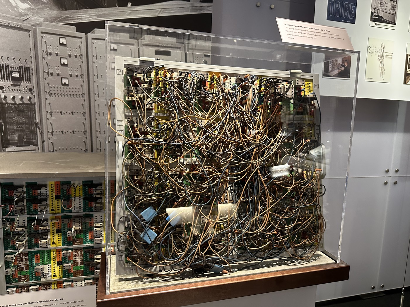
Figure 4 — An EAI 580 patch panel, preserved with a program still on it. This is what a substantial analog computer program physically is, and why removable problem boards existed. Photograph: File:EAI 580 patch panel.agr.jpg by ArnoldReinhold, CC BY 4.0, via Wikimedia Commons.
Figure 4 is included as a caution rather than an aspiration. A patched program is state that exists nowhere else: there is no file, and re-running last month’s work means patching it again from the flow diagram. The commercial answer was the removable pre-patch panel — lift the whole program out, store it, drop in another.
No homebrew design in this survey has one, and for machines of four to ten elements none needs one. The obligation the absence creates is documentary: the patch diagram is the source code, and a machine without a disciplined habit of drawing and keeping them will lose every program it ever runs. Vol 6 §2 treats the flow diagram as a working document for exactly this reason.
5.8 Power and the Sensitive Nodes
5.8.1 Rails
A computing machine wants ±15 V if the format allows it, for the headroom argument in §3.4. It wants linear regulation rather than switching, because switching noise on the rails reaches the summing junctions. And it wants the reference derived separately from the rails, not tapped from them, for the reasons in Vol 2 §6.
5.8.2 Keep Switching Currents Off the Computing Rails
Vol 4 §5.3 noted Fitch’s dedicated µA78M12CKC producing a 12 V rail for the relay coils alone. This is the single most transferable power-supply decision in the survey. Relay coils, and any digital or switching circuitry, draw current in abrupt steps; a computing amplifier’s rails should not carry those steps. The same reasoning is why the Synthesizers.com format separates its +5 V digital supply from the ±15 V analog supply explicitly.
5.8.3 The Three Nodes That Need Care
Almost all of a homebrew analog computer’s layout is undemanding. Three nodes are not:
Table 5 — Almost all of a homebrew analog computer's layout is undemanding. Three nodes are not
| Node | Why | Practice |
|---|---|---|
| The summing junction | High impedance, and the point at which every error current is indistinguishable from signal. Also where stray capacitance causes the ringing that Fitch’s optional 27 pF addresses | Keep the physical node small. Every patch cord landing on it adds capacitance and leakage paths |
| The integrating capacitor | Its leakage and dielectric absorption enter the answer directly (Vol 3 §4) | Keep it close to the amplifier. Routing it through a patch cord and two jacks, as a switchable-capacitor panel does, is a real cost paid for real flexibility |
| The reference distribution | Every coefficient is a fraction of it, so a drop along the distribution is a scale error in every coefficient fed from the far end | Distribute as a star from the reference, not as a daisy chain down a bus |
The third is easy to get wrong on a bussed machine and invisible when it is wrong, because every coefficient is slightly off in the same direction and the machine still produces a plausible curve.
5.9 Choosing
Table 6 — Choosing
| If the machine is… | Substrate |
|---|---|
| Four to eight elements, known complement, cheapest possible | Single board |
| Intended to grow, up to about ten elements, parts to be bought not made | Eurorack mechanics with purpose-built computing modules and a private mode bus |
| Intended to grow past ten elements | Eurocard and DIN 41612 with a designed backplane |
| Modest, and electrical margin matters more than size | Synthesizers.com 5U, for the ±15 V rails |
| A period reproduction, or a one-off with unusual mechanics | Hand-wired chassis |
The row most often chosen by accident is the second, and it is a good choice provided the builder knows they are buying mechanics and power, not an architecture. The three missing subsystems in §3.3 are the entire difference between a case full of modules and a computer.
5.10 What Comes Next
Vol 6 moves from hardware to use: amplitude and time scaling, the flow diagram as source code, worked programs and the static check-out that catches a wrong patch before it produces a plausible answer. Vol 7 returns to licences and sets the modern machines against the 1960s ones, including a substrate comparison — because the shift from hand-wired chassis to fabricated boards is one of the clearest departures in the record.
Comments (0)