Homebrew / Open-Source · Volume 4
Homebrew & Open-Source Analog Computers — Volume 4 — The documented designs, read as engineering
Six machines from 1968 to 2022, each read for the decisions it made, the constraints behind them, and what the surviving documents do and do not establish
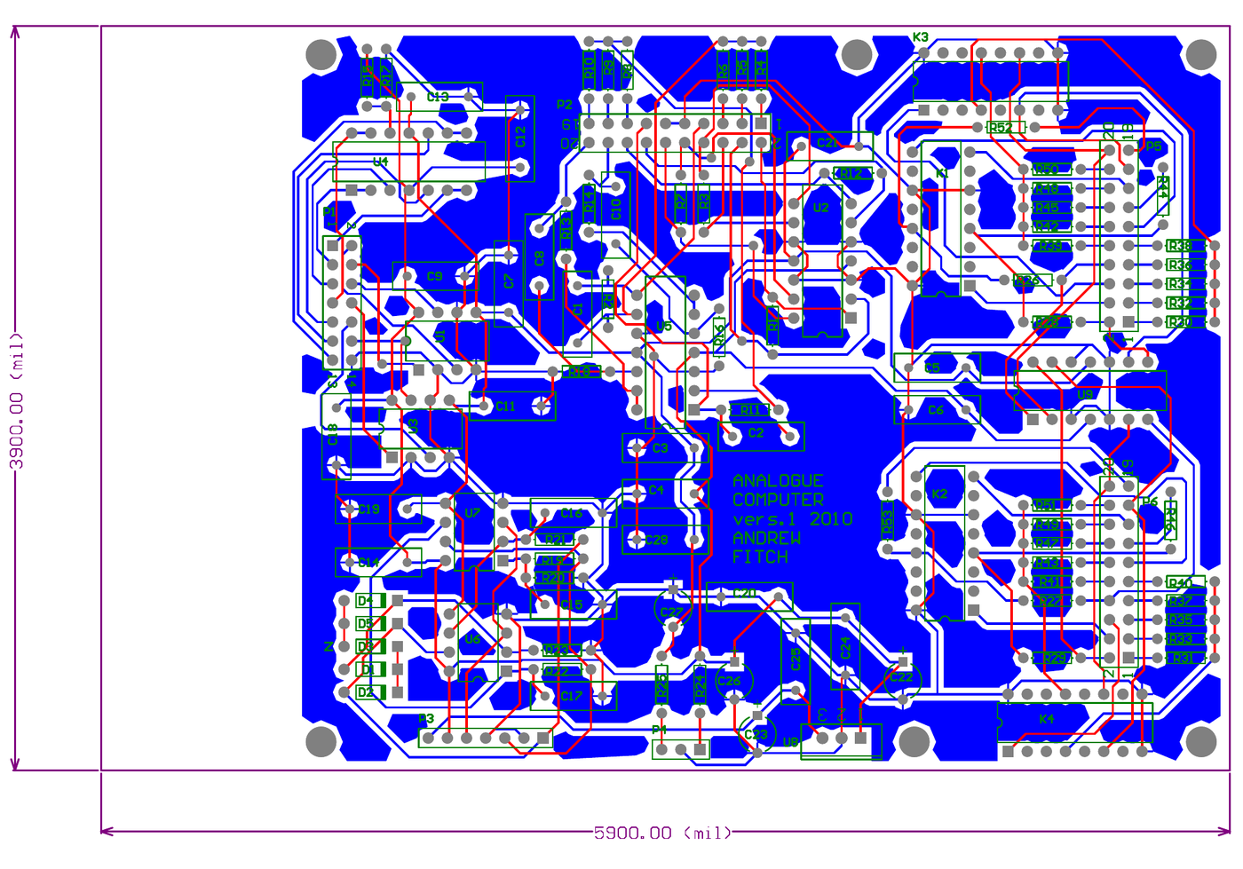
Figure 1 — The board that carries most of a homebrew analog computer: Fitch’s 2010 layout, 5900 × 3900 mil (about 150 × 99 mm), with the four integrator relays ranged down the right-hand side and the designer’s name and version in the silkscreen. Design document held locally; provenance and licence status in photo_credits.txt.
4.1 About This Volume
Vols 2 and 3 set out what a homebrew analog computer has to contain and which parts of it are difficult. This volume goes to the record and reads six designs against that framework.
The reading is deliberately uneven, because the sources are. Two of these designs are multi-part constructional series written to be followed by strangers; one is a complete set of schematics, board files and panel artwork published without a word of licence; one is a thesis; one is a forum thread spanning years; and two are repositories. Each is read for what its own documents establish, and the places where they establish nothing are marked rather than filled.
Cross-references: Vol 1 §5 for the census these six are drawn from; Vol 2 and Vol 3 for the element and mode-control framework applied here; Vol 7 for each design’s licence position.
4.2 How These Designs Are Read
Six questions are asked of each, chosen because they are the decisions that determine what the machine can do:
- What is the machine unit, and what are the rails?
- How many of each computing element, and how are they multiplied?
- How is mode control implemented?
- What is the substrate — board, chassis, module format?
- What diagnostics does it provide?
- What did the designer say the machine was for?
The sixth turns out to be the most predictive. Machines built to produce numbers and machines built to produce pictures diverge early and thoroughly, and most of the apparent inconsistencies in the record dissolve once the intended use is known.
4.3 PEAC — Practical Electronics, 1968
“A low cost, general purpose analogue computer of modern design, intended for the amateur or student.” The opening line of the series states the position exactly.
PEAC is the earliest design in the survey and the one most conscious of being an entry point. Its central architectural decision is modularity as an affordability strategy: the machine is arranged in units A through D, and the series is explicit that “reasonably advanced computations may commence upon completion of the first unit”. Unit A alone — costing, the article says, “not much above £25” at the time of writing — would “solve algebraic polynomial equations, simultaneous linear equations, simple differential equations”. Units B, C and D add a function generator, a multiplier and fuller integrating facilities, with a comprehensive installation reaching “around £60”.
Two things stand out when this is read as engineering rather than as history.
The first is that PEAC’s pitch rests on timing, not accuracy. The series claims a typical solution arrived at in 20 ms, repeatable “at the rate, say, of 25 solutions per second”, and argues that this immediacy is the point: “any adjustments made to problem parameters while the computer is working will be immediately reflected in the solution readout”. That is repetitive operation used as an interactive medium, and it is the same argument THE ANALOG THING makes fifty-three years later.
The second is the frank multi-purpose sales case. The article offers the finished machine as “a variable waveform generator, 18 input high quality audio mixer, variable characteristic high Q audio filter, large inductance or capacitance simulator, d.c. or a.c. millivoltmeter, and many other things besides”. This is a constructional magazine justifying a £60 outlay, but it is also an accurate observation about what a rack of summers, integrators and pots physically is — a point Vol 5 §6 returns to when it examines whether synthesiser modules can be turned into an analog computer.
The design is described as becoming possible only once “the silicon transistor had become firmly established”, which dates the technology precisely: PEAC is a discrete solid-state machine, predating the general availability of the monolithic op-amps that every later design in this survey takes for granted.
4.4 Kronis — Practical Electronics, September–December 1978
P. J. Kronis’s four-part series is the most complete homebrew construction project in the survey, and it is the one that most resembles a commercial machine in its provisions.
Table 1 — Kronis — Practical Electronics, September–December 1978
| Question | Answer |
|---|---|
| Elements | Ten computing amplifiers — summers and integrators — built on 741 op-amps |
| Multiplication | Two AD533JD four-quadrant multiplier ICs |
| Mode control | Relay-based Compute / Hold / Reset, with initial conditions |
| Patch field | 148 sockets, colour-coded |
| Diagnostics | Overload warning circuit with comparators and LEDs |
| Substrate | Main PCB carrying all ten computing elements, into a case, with eight edge connectors |
The part worth dwelling on is the overload circuit, because Vol 3 §6.1 argued that its absence is the commonest gap in homebrew design. Kronis includes it, in an amateur constructional series, across all ten amplifiers — which is a fair measure of how necessary a working analog-computer designer considered it in 1978. The same series devotes its third part to “offset-null trimming and mode-control testing of all ten computing amplifiers”, which is the balance procedure Vol 3 §5 identified as the single highest-value facility a machine can have.
The series is also unusually honest about its own errors in a way that is instructive. Part 4, the December 1978 conclusion, carries a corrected patch-panel diagram replacing a misprint in Part 3 — a reminder that the patch field is the machine’s user interface, that an error in its documentation is an error in the machine, and that this was as true for a magazine in 1978 as it is for a repository today.
The programming content across Parts 3 and 4 is substantial: ramp and square-law function generation, initial conditions, the spring-mass oscillator, damping under impulse, step, sinusoidal and random forcing, Lissajous figures, a lunar-lander flight simulation with both amplitude and time scaling, and a survey of diode limiters, dead-zone, absolute-value and flip-flop circuits. Vol 6 draws on several of these.
4.5 Vogel, c. 2005 — and the Substitution Problem
The Vogel design occupies an unusual position: it circulated as a set of printed circuit boards distributed by the designer rather than as a published article, and the document held in this project is not the design itself but an account of building one.
That account is the most useful thing in the survey for a practical builder, because it is a detailed record of what happens when a design meets a parts shortage. The builder records three substitutions and the consequence of each:
Table 2 — That account is the most useful thing in the survey for a practical builder, because it is a detailed record of what happens when a design meets a parts shortage. The builder records three substitutions and the consequence of each
| Original part | Substituted | Consequence recorded |
|---|---|---|
| LF355 / LF353 amplifiers | TL081 / TL082 | The zero-correction polarity is opposite. The TL081 requires a negative bias voltage for zero correction where the LF355 requires a positive one. Rather than rework the circuit, the builder bent up pins 1 and 5 on every device and ran without zero adjustment until correct parts could be obtained |
| AD534K multiplier | AD734 | Pins 3, 4 and 5 must be tied to ground for correct operation in this context |
| Precision positive machine-unit regulator | LM317 | Described by the builder as “cheap and imprecise”, requiring small circuit changes |
| SMD resistors | Axial resistors | Worked without difficulty |
The first row is the one to remember. Two op-amps in the same package with the same pinout and the same function have offset-null pins that want opposite polarities, and the failure mode is not a dead circuit but an amplifier that cannot be balanced — precisely the facility Vol 3 §5 identified as the most valuable in the machine. A builder substituting parts on any of these designs should check the null arrangement specifically, because it is the detail most likely to be pin-compatible and functionally incompatible.
Two mechanical notes from the same account round out the picture: the board material was too thin to support the 10-turn precision potentiometers, requiring fabricated spacers, and the machine uses 2 mm jacks for its patch field — the small-format choice Vol 5 §4 examines.
4.6 Fitch, 2010 — “Analogue Computer vers.1”
This is the design documented in most complete detail in this project: panel artwork, three schematic sheets, a PCB layout, a bill of materials and the designer’s own project page. It is read here at length because the documents support it.
4.6.1 What It Contains
From the panel artwork and schematics: four summer/integrators, two summers, four inverters, two four-quadrant multipliers, two gyrators, a quadrature oscillator, three adjustable buffered 0–10 V sources, four free 100 kΩ potentiometers, and patchable free components — three capacitors of 0.01, 0.1 and 1.0 µF, six signal diodes, and five zener diodes, three of 3.6 V and two of 5.1 V.
The computing core is conventional and well executed. The integrators use 1 MΩ and 100 kΩ input resistors for the standard weight-1 and weight-10 inputs, a DPDT relay each for mode control, and 100 kΩ feedback around the relay network. The summers use 1 MΩ feedback with 1 MΩ and 100 kΩ inputs, with optional 27 pF across the feedback resistor to tame summing-junction stray capacitance (Vol 2 §3.1).
4.6.2 The Unconventional Parts
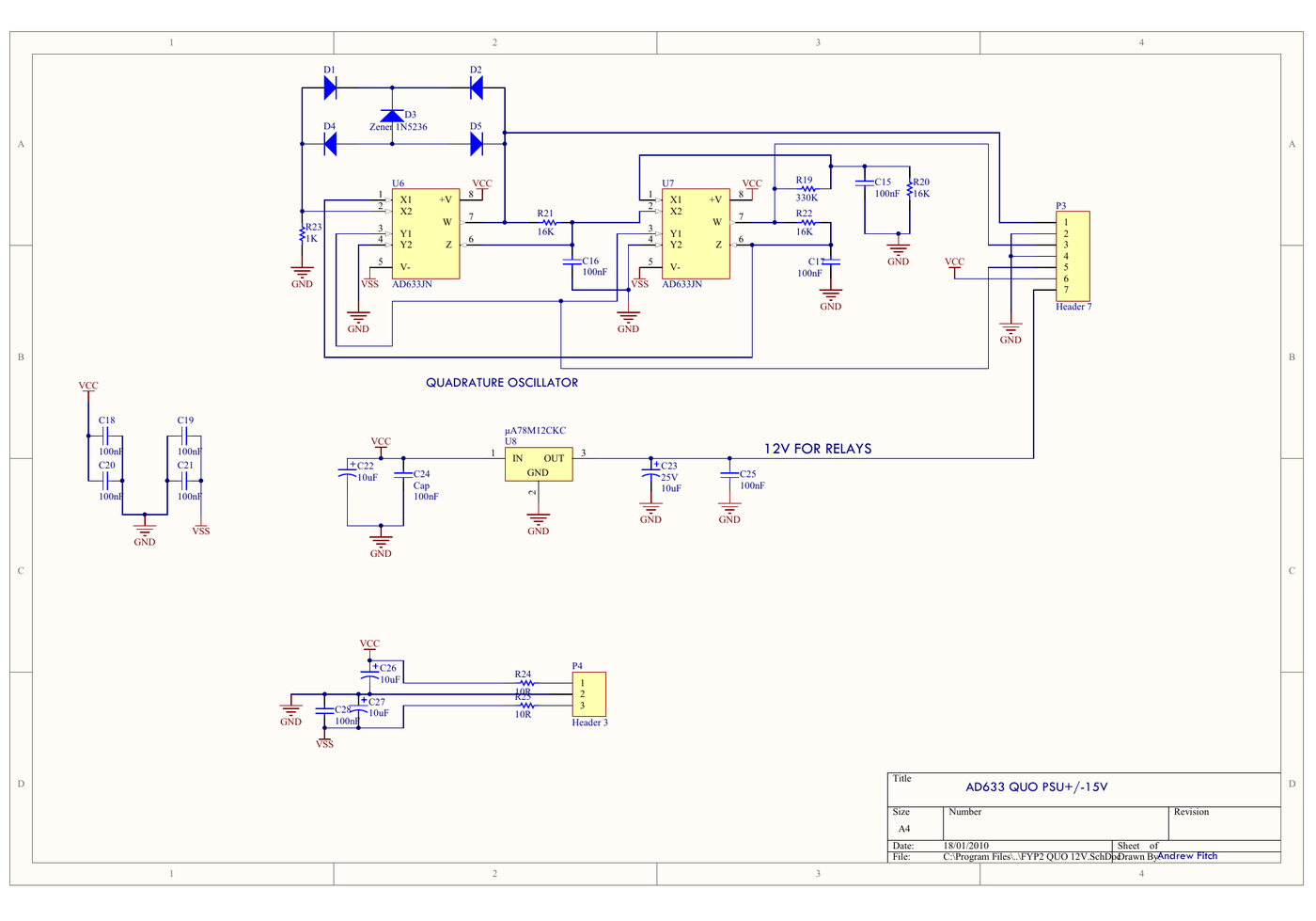
Figure 2 — Sheet 3 of 3. The quadrature oscillator is built from two AD633 multipliers with a diode-and-zener limiting network setting the amplitude; below it, the µA78M12CKC regulator produces the separate 12 V relay rail discussed in Vol 3 §3.1. Design document held locally.
Three features would not appear on a commercial machine, and each tells you what the machine was for.
The gyrators. Two op-amp circuits simulating grounded inductors of 1 H and 10 H. The panel description is explicit that these are “usually not included in analogue computers but have been in this unit for studying Chua oscillators”. A Chua circuit needs an inductor; the machine was built by a designer whose doctoral work was on memristor-based chaotic circuits; the element set was extended to suit.
The quadrature oscillator, giving simultaneous sine and cosine from below 1 Hz to almost 10 kHz at approximately 6 V peak-to-peak, the amplitude varying slightly with frequency. Built into the panel rather than supplied externally, it makes the machine self-contained for driven-system work.
The free component bank. Loose diodes, zeners, capacitors and potentiometers brought to jacks, so that non-linearities can be patched rather than designed in. This is the cheapest possible route to limiters, dead zones and comparator-like behaviour, and it is a deliberate choice in favour of flexibility over accuracy.
4.6.3 The Supply, and a Design Decision Worth Quoting
The machine runs from a 15 V AC adapter into a bipolar ±15 V supply on a separate board, and the designer states plainly why that supply was bought rather than designed: “1 to keep mains voltages away from the device, 2 it is cheaper to buy a kit from Jaycar than to get PCBs manufactured and source the necessary components.”
That is the homebrew economics of Vol 1 §3 stated in one sentence, and it is correct reasoning. Separately, the relay coils get their own 12 V rail from a µA78M12CKC so that coil transients stay off the computing rails.
4.6.4 What the Documents Do Not Establish
Three points, marked because the temptation to smooth them over is real:
- The build state. The project page, dated FEB2010, says the schematics and panel designs “at this point (6/3/10) are untested, I still have to wire this up”, and mentions “only two errors noticed on the boards…so far”. The same page later reports a working Lorenz attractor with the bugs and spurious oscillations sorted out. The machine evidently worked; which revision the documents describe is not established.
- The device count. The bill of materials for the project lists three TL074J and four AD633JN. The schematic sheets show a quad op-amp dedicated to the four integrators in addition to the quads used for summers, inverters, buffers and gyrators, which does not reconcile with a total of three. The most likely explanation is that the integrator sheet is a separate board with its own designator sequence and the bill of materials covers only the second board — but that is inference, and the held documents do not settle it.
- No licence. Nothing in the panel artwork, the schematics, the bill of materials or the project page states any licence terms. See Vol 7 §2.
4.6.5 What It Was For
Stated directly on the project page: a device to simulate physical systems, “intended for studying simple chaotic circuits, although more complex circuits can be created using two modules”, and usable “as a training device for EE courses; particularly in control engineering and filter design”. Every unconventional decision above follows from that first clause. The machine was built to produce pictures of chaotic attractors, and it is optimised accordingly — which is why it carries gyrators and a sine source but no overload detection and no coefficient readout.
4.7 Malmö, 2022 — The Thesis Machine
Carl Oskar Ahlqvist and Måns Ahlgren’s master’s thesis at Malmö University designs, builds and evaluates a low-cost modular analog computer in a single-board form factor, capable of solving second-order differential equations, and evaluates two hardware revisions, V1 and V2.
The parts, from the V2 bill of materials: TL074 quad op-amps (four), AD633JNZ multipliers (three), an NJU7662 voltage converter, 1 MΩ, 1 kΩ and 100 kΩ resistors, 9 mm potentiometers, a toggle switch and per-integrator buttons and capacitor headers.
The NJU7662 is the detail worth noting. It is a charge-pump voltage converter, and its presence indicates a machine generating its negative rail on-board from a single supply rather than taking a bipolar input. That is a reasonable decision for a low-cost single-board machine and a compromise on supply quality, since a charge pump is a switching device sitting on the rails that feed the computing amplifiers.
The evaluation is done by demonstration rather than by measurement: the machine is exercised on Mathieu’s differential equation and a spring-mass damping system, with the thesis reporting qualitative agreement. Consistent with Vol 1 §6, no measured error figure against a known solution is reported.
The framing argument is the modern one and is worth recording because it is why this machine exists: the thesis argues that digital computing’s energy consumption is the constraint that makes analog and hybrid systems relevant again, and that for the field to progress “it must be made accessible to a wider group of people compared to today”. The artifact is offered as a step toward that accessibility. Vol 7 §5 treats this argument and its limits.
4.8 The EEVblog Machine, 2012 Onward
The forum thread started by the contributor “GK” in November 2012 documents the most ambitious machine in the survey, and the only one whose stated primary goal is precision.
Its defining decision is the machine unit. Where every other design in this survey uses ±10 V, this one uses ±100 V, on regulated ±110 V rails, and the rationale is explicit: a larger signal reduces the relative significance of amplifier input offset, diode forward drops and similar fixed error terms. This is the 1950s and early-1960s professional convention — the Heathkit EC-1 worked at ±60 V, the large EAI installations at ±100 V — deliberately revived against the modern ±10 V norm. Vol 7 §4 treats it as the single clearest counter-example to the claim that modern reimplementations simply improve on the old machines.
The element work documented in the thread is at a level no other homebrew design in the survey approaches:
Table 3 — The element work documented in the thread is at a level no other homebrew design in the survey approaches
| Module | Documented design |
|---|---|
| Sine/cosine function generator | Piecewise approximation with breakpoints at 90° and 270°; 1 MΩ input impedance; ±10 mA output |
| Logarithmic amplifier | SSM2212 matched transistor pair with thermistor compensation; input range 0.01 V to 100 V; better than four decades |
| Exponential amplifier | The inverse function, same approach |
| Triangle generator | Fixed 500 Hz, for calibration by total-harmonic-distortion analysis |
| Iteration counter | Four-bit programmable, sixteen decimal outputs plus BCD, for varying problem constants between runs |
Named parts include the LT1097 precision op-amp and the LT1634 reference, the latter reportedly replaced later by a 0.1 % resistor ladder on cost grounds. The intended physical form is a floor-standing 19-inch rack of roughly two metres.
The thread also records a design error and its correction — a misplaced decimal point in the logarithmic amplifier’s resistor calculation, requiring R8 to change from 10 Ω to 100 Ω — which is a useful reminder that the most carefully engineered machine in the survey still shipped an arithmetic slip into a published schematic.
What the held material does not establish is whether the machine was completed. The surveyed portion of the thread shows PCB layouts in progress and components being procured as of early 2013. Vol 7 §6 lists this among the open questions.
4.9 The Repositories
Three GitHub projects complete the census. They are grouped because what they share — public version control, a permissive licence, and incompleteness — is more significant than their individual designs.
Table 4 — The Repositories
| Repository | Licence | Contents | State |
|---|---|---|---|
danja/analog-computer | MIT | Front-panel design with 2 mm colour-coded sockets, module definitions for summers with summing-junction access, integrators and differentiators, SPICE work, a development log, reference notes | Design and research substantially advanced; breadboarding and assembly incomplete. The author describes it as “in need of organization” |
Marbslab/Analog-computer | MIT | Gerbers, two schematic PDFs, a spreadsheet bill of materials, STL files for an arm, base plate, DSO138 oscilloscope enclosure and voltmeter bracket, and a photograph of the finished unit | Hardware files present and apparently complete; essentially no written documentation |
PrasannahRam/ANALOG_COMPUTER | None | Adder, subtractor, multiplier, integrator and differentiator circuits around NE5532 op-amps, with power-supply design documentation | Early |
The second row is the interesting one. Marbslab’s repository contains everything needed to fabricate the machine — board files, parts list, printed mechanical parts — and almost nothing explaining it. That is the exact inverse of the magazine series, which explained thoroughly and shipped no files. Neither is complete, and the two failure modes are symmetrical: a design that cannot be understood and a design that cannot be reproduced.
The DSO138 enclosure in that same list deserves a note, because it is a genuinely modern move. The DSO138 is an inexpensive single-channel oscilloscope module, and designing it into the machine’s physical structure means the readout is part of the computer rather than an instrument beside it. The 1960s equivalent was a panel meter and a null pot; Vol 7 §4 counts this among the real departures.
4.10 Comparison
Table 5 — Comparison
| PEAC 1968 | Kronis 1978 | Vogel c.2005 | Fitch 2010 | Malmö 2022 | EEVblog 2012– | |
|---|---|---|---|---|---|---|
| Machine unit | not established | not established | not established | ±10 V panel sources | not established | ±100 V |
| Amplifiers | discrete silicon | 741 | LF355/LF353 | TL074 | TL074 | LT1097 |
| Multiplier | discrete, optional unit | 2 × AD533JD | AD534K | 2 × AD633JN | 3 × AD633JNZ | log/antilog pair |
| Mode control | integrator mode switching | relay | not established | 4 × DPDT relay | board switch and buttons | not established |
| Overload detection | not established | yes | not established | none | not established | not established |
| Substrate | modular units A–D | single main PCB | PCB set + panel | 150 × 99 mm PCB + Pactec case | single board | 19-inch rack |
| Built for | teaching, amateur use | teaching, amateur use | teaching | chaotic circuits | thesis demonstration | precision |
4.11 Six Lessons From the Record
Intended use predicts every other decision. Read the “built for” row, and the rest of each column follows. This is the most reliable interpretive tool in the survey.
The magazine series document better than the repositories do. Both 1970s entries explain their circuits, their construction, their testing and their programming. The repositories ship files. A reader wanting to understand an analog computer is better served by 1978 than by 2024, which is not a comfortable conclusion.
Substitution is where builds fail, and null arrangements are the trap. The Vogel account’s opposite-polarity offset-null pins is the single most transferable warning in this volume.
Nobody measures. Six designs, five decades, and not one reported measurement of solution error against a known result. Accuracy claims in this field are component specifications, not machine specifications.
The unconventional features are the interesting ones. Gyrators for Chua circuits, ±100 V rails, an oscilloscope module built into the chassis, an iteration counter for parameter sweeps. None would survive a product review; all of them are why these machines are worth reading about.
Errors get published. A misprinted patch-panel diagram in 1978, two board errors in 2010, a decimal-point slip in 2012. Each was found and corrected in public, which is an argument for the constructional-series and forum-thread formats over the silent repository.
4.12 What Comes Next
Vol 5 takes the physical substrate these designs chose between — board, chassis, module format, jacks, panel and power — and addresses the recurring question of whether an existing modular synthesiser format can be pressed into service. Vol 6 turns to programming, using worked examples drawn from several of the designs above. Vol 7 returns to each design’s licence position and sets the modern machines against their 1960s ancestors.
Comments (0)