GE Project EF-140 · Volume 4
GE Project: Analog Computer EF-140 — Volume 4 — Operating it
Calibration against a known product, scale plates and memory boards, the null by ear, and the two corrections General Electric issued after publication
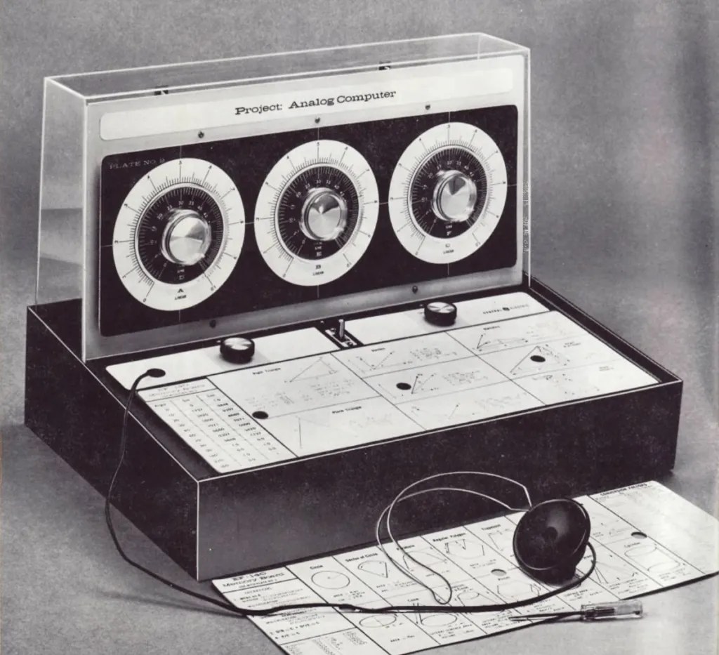
Figure 1 — The machine set up for work. A scale plate is fitted over the three pot shafts; a memory board — the formula sheet printed on the reverse of a different scale plate — lies on the horizontal panel where the operator can read it. The earphone is the readout. Photograph: General Electric publicity image.
4.1 About this Volume
This volume covers everything between a finished kit and an answer: the two preliminary steps General Electric requires before any problem is attempted, how the scale plates and memory boards work together, the technique of finding a null by ear, and the two corrections issued in the manual’s addendum sheet.
The operating procedure is short — the machine has three knobs that compute and two that do not — but two parts of it repay attention. The calibration procedure is a small piece of design cleverness (§2), and the scale-plate-and-memory-board arrangement is a genuinely thoughtful solution to a problem the kit created for itself (§4).
Cross-references: Vol 2 for the circuit that makes this procedure work; Vol 3 for construction; Vol 5 for what the scales themselves do; Vol 6 for the problems.
4.2 Calibration
4.2.1 The Procedure
The manual’s Part 5 opens with two “essential preliminary steps… You must calibrate it, that is, adjust it to give correct answers. And you must install a Scale Plate appropriate to the problem you wish to solve.”
Calibration, in full:
“Install any scale plate you wish on the dial board. Simply remove the scale knobs, slip the scale plate over the three pot shafts and put the knobs back.
Turn the on-off switch to on. Set dial X at .6 on Scale A (the outside scale). Set dial Y at .7 on Scale B. Set dial Z at .42 on Scale C. Listen in the earphone. Turn the calibrate knob until you hear no sound. The currents are then properly divided between the problem and answer portions of the computer, and the computer is calibrated for proper operation.”
4.2.2 Why This Is Well Designed
The three settings are not arbitrary:
0.6 × 0.7 = 0.42The calibration is itself a multiplication whose answer is already known. The operator sets a problem and its correct answer simultaneously, then adjusts the one remaining control — the calibrate pot — until the machine agrees.
This is better than a conventional zero adjustment in three ways. It exercises all three computing potentiometers at once rather than checking an endpoint. It calibrates at mid-scale, where the machine will actually be used, rather than at zero where errors are smallest and least informative. And it teaches the operating technique — set two dials, null the third — during the very first action performed on the machine. A student who has calibrated the computer has already multiplied on it, and the manual says so a page later: “As you may have noticed, you have already carried out a multiplication. To calibrate your computer, you multiplied .6 by .7 and adjusted the calibrate knob to give the known result, .42.”
4.2.3 When to Recalibrate
“The computer need not be adjusted between problems, but you should re-calibrate it each time you sit down to work with it.”
Per-session rather than per-problem. What drifts between sessions is battery voltage and contact resistance; neither changes appreciably over the course of an afternoon. What the calibrate pot is trimming out is the ratio between the two branches of the bridge (Vol 2 §4.1), and that ratio is stable while the machine is switched on.
4.2.4 If It Will Not Calibrate
The manual gives one fallback, and it is unusually specific for a kit manual:
“If you cannot calibrate the computer this way, remove the two 33-ohm resistors from the calibrate pot, and try calibrating again.”
R-6 and R-7, the two 33 Ω resistors, sit across the calibrate potentiometer — one between terminals 1 and 2, the other between terminals 2 and 3 (Vol 3 §4.4). They pad the pot, reducing its effective range so that the calibration adjustment is fine rather than coarse. Removing them widens the adjustment range at the cost of sensitivity.
That this instruction exists at all implies General Electric knew the padded range was marginal on some units — presumably because of accumulated tolerance in the potentiometers and the battery voltage. It is effectively a factory-sanctioned rework, printed in the manual before the machine ever reached the customer.
4.3 The Tone Control
The second preliminary is optional and takes a moment:
“The tone control changes the tone or pitch of the sound you generated in the earphone, not the volume or loudness. To adjust the tone, simply turn the knob until the earphone generates a satisfactory tone.”
R-2, the 200 kΩ pot, sets the multivibrator’s frequency (Vol 2 §7.1). The manual presents this as comfort — “so that the tone generated by the earphone is pleasing to your ear” — and it is, but it is not only that.
This series’ observation: the ear’s ability to detect a small residual tone against silence depends on frequency. Sensitivity peaks in the region of two to four kilohertz, and a null found at a pitch where hearing is acute can be located more finely than one found at a pitch where it is not. The tone control is therefore also a resolution adjustment, though neither the manual nor, presumably, most operators would have described it that way. An operator wanting the best possible reading should set the tone as high as remains comfortable rather than as low.
4.4 Scale Plates and Memory Boards
4.4.1 What They Are
Three scale plates, each a card that slips over the three potentiometer shafts so that the dial knobs read against it. Each plate carries a different set of scales, and therefore turns the same three potentiometers into a machine for a different class of problem.
Table 1 — 4.1 What They Are
| Plate | Scales | Problems it serves |
|---|---|---|
| No. 1 | A, B, C linear; D, E, F logarithmic | multiplication, division, powers, roots, logarithms |
| No. 2 | A, B, C linear; D, E, F sine and cosine | trigonometric functions |
| No. 3 | square and reciprocal scales | multiple operations without resetting dials |
Changing plates is trivial: “scale plates are simply changed by removing the scale knobs from the pot shafts.”
On the reverse of each plate is a memory board — a printed sheet of formulas, conversion factors and computational aids. The manual describes them as “a handy ‘formula dictionary’ to enable you to solve the greatest variety of problems”, and notes that they carry far more than the manual discusses: “The memory boards contain many more formulas than can be discussed in the manual.”
4.4.2 The Cross-Linking
Here is the piece of design worth pointing at. The plates are arranged so that the memory board a given plate needs is printed on the back of a different plate:
“The scale plates are so arranged that when you install Scale Plate No. 1 in your computer, for instance, the accompanying memory board will be on the reverse side of one of the other scale plates.”
The replacement-parts list confirms the pairing explicitly: EK-245 is “PLATE #2 SIN COS SCALE w/MEMORY BOARD FOR PLATE #1”, and EK-246 is “PLATE #3 SQUARE-RECIPROCAL SCALE w/MEMORY BOARD FOR PLATE #2”.
The problem this solves is obvious once stated: a card cannot be read on both sides at once. If plate 1’s formulas were printed on plate 1’s back, installing plate 1 would hide exactly the formulas needed to use it. By rotating the assignment, the operator installs one plate on the dial board and lays another face-up on the horizontal control panel, where the manual intends it to go: “place the appropriate memory board on the horizontal control panel in front of you and go to work.”
The horizontal panel exists partly to be a lectern. That is why it is horizontal, and it is why the finished machine has a flat surface in front of the operator that carries only two small knobs.
4.4.3 What This Implies About the Machine
Vol 2 established that the circuit performs exactly one operation. This section establishes the corollary: the machine’s mathematical range is a printing problem, not an electrical one. New capability arrives as a new card. A fourth scale plate would have extended the machine without altering a single component — and, conversely, an EF-140 that has lost its scale plates has lost almost all of its function while remaining electrically perfect.
For a surviving machine, the plates are the parts to worry about.
4.5 Finding a Null
4.5.1 The Basic Action
“Set the pointer of dial X to .8 on Scale A. Set dial Y to .4 on Scale B. Now turn the pointer of dial Z until you hear no sound in the earphone — in other words, until the voltage from pot Z balances the voltage from pot Y and no tone current reaches the earphone… When you have thus turned the dial to ‘null,’ read the pointer setting on Scale C. It should be .32.”
And 0.8 × 0.4 = 0.32. ✓
4.5.2 Technique
This section is this series’ practical guidance; the manual gives only the instruction above.
The null is a minimum, not a switch. Approaching it, the tone falls; past it, the tone rises again. Three consequences for technique:
Bracket rather than hunt. Turn until the tone rises again, note the position, reverse, note where it rises on the other side, and take the midpoint. The centre of the quiet band is a better estimate of the null than the quietest point the ear can identify, because the ear’s discrimination is poorest exactly where the signal is smallest.
Expect a band, not a point. Below some residual level the tone becomes inaudible over a small range of dial positions rather than at a single one. The width of that band is the machine’s resolution at that setting, and it is a fair indication of how many figures the reading deserves.
Approach from the same side each time. Any mechanical linkage has backlash, and a dial-and-shaft arrangement fixed with a set screw has more than most. Consistently approaching from one direction removes it from the answer.
4.5.3 What Silence Guarantees
Vol 2 §6.2 made the argument in full; the operational summary is that at null the earphone carries no current, so nothing about the earphone, the transistors or the battery voltage affects the result. The reading depends only on the three dial positions. This is why a machine whose tone has gone weak — flat batteries, tired earphone — still gives correct answers, merely harder-won ones. A weak tone costs resolution, not accuracy.
4.6 The Addendum
The manual as held carries a separate addendum sheet, evidently issued after publication, containing two items. Both matter operationally.
4.6.1 The Division Correction
“In solving division problems, such as Problem [4] on Page 26, you will note that it is necessary to adjust the numbers so that you will have Dial C turned farther to the left than Dial B. This means that in order to obtain a null on Dial A, you must set the pointer on Scale C to .095 (located between 0 and .1). Then, set the pointer on Scale B to .48. Now, rotate the dial on Scale A until you get a null at the answer, which should be at .198. Of course, you must readjust the decimal point in the answer to get 198. In other words, in all division problems, if you are unable to tune to a null on Scale A, then readjust the setting on Scale C so that it is turned further to the left than Scale B.”
The problem referred to is 95 ÷ 0.48, whose listed answer is 198.
The arithmetic of the workaround checks out:
0.095 / 0.48 = 0.19792 ≈ 0.198and the true value is 95 / 0.48 = 197.9 ≈ 198. ✓
Why the correction is needed. The null condition is k_Z = k_X · k_Y. Since every k lies between 0 and 1, the product k_X · k_Y can never exceed either factor. So a null is only reachable if k_Z ≤ k_Y — the dividend setting must not exceed the divisor setting. Written the natural way, 95 ÷ 0.48 would want k_Z = 0.95 and k_Y = 0.48, and 0.95 > 0.48, so no setting of dial X can balance the bridge. Rescaling the dividend by a further factor of ten, to 0.095, brings it under 0.48 and the null becomes reachable. The factor of ten is then carried in the decimal point.
The general rule the addendum states — “if you are unable to tune to a null on Scale A, then readjust the setting on Scale C so that it is turned further to the left than Scale B” — is exactly this constraint, expressed as something the operator can see on the dials.
Note — This is a genuine limitation of the machine, not a mistake in the manual, and it is the clearest illustration of the boundedness of k that Vol 2 §3.2 identified. The original text simply failed to warn about it, and the addendum is the correction.
4.6.2 The Accuracy Adjustment
“ACCURACY: You may increase the degree of accuracy of your computer by making the following adjustments:
- Loosen the retaining nuts on dial potentiometers X, Y, and Z.
- Next, rotate the three dials to the extreme counter-clockwise position which will put the hairline on, or below, the zero point on the scale. Keeping the dials in this position, re-tighten the retaining nuts, making sure the locating tabs on the potentiometer are in their holes.”
This aligns each potentiometer’s mechanical end-stop with the zero of its printed scale. Without it, a pot mounted a few degrees out of true reads a constant angular offset on every setting — a systematic error affecting every problem, and one that calibration at a single point cannot remove, because calibration trims the ratio between branches, not the angular registration of the dials.
That this appears on an addendum rather than in the assembly instructions suggests it emerged from returned units. Step 3 of the assembly (Vol 3 §4.1) says only to secure each pot “so that the pot is held securely and will not turn when the dial knobs are attached” — it says nothing about where to hold it.
For anyone operating a surviving EF-140, this is the first adjustment to make. It is free, reversible, and corrects a systematic error.
4.7 The Operating Sequence
Assembled from the manual’s instructions:
Table 2 — Assembled from the manual's instructions
| # | Action |
|---|---|
| 1 | Check that the dials are aligned to their potentiometers’ zero (§6.2) — once, not per session |
| 2 | Select the scale plate for the class of problem; fit it over the three shafts; replace the knobs |
| 3 | Lay the matching memory board face-up on the horizontal control panel (§4.2) |
| 4 | Switch on |
| 5 | Adjust the tone to a comfortable, reasonably high pitch (§3) |
| 6 | Calibrate: X = .6 on A, Y = .7 on B, Z = .42 on C, turn CALIBRATE to silence (§2) |
| 7 | Scale the problem’s numbers into the 0-to-1 range, recording the powers of ten (Vol 5) |
| 8 | Set the two known quantities on their dials |
| 9 | Turn the third dial to null, bracketing rather than hunting (§5.2) |
| 10 | Read the answer; restore the decimal point from the powers recorded at step 7 |
Steps 7 and 10 are where the operator does the work the machine cannot, and they are the subject of the next volume.
4.8 What Comes Next
Vol 5 covers the mathematics carried by the printed scales: the powers-of-ten discipline that steps 7 and 10 above require, and how logarithmic, trigonometric, square and reciprocal scales extend three potentiometers to a far wider range of problems than the circuit alone could reach. Vol 6 works through the forty-nine problems General Electric set.
Comments (0)