GE Project EF-140 · Volume 1
GE Project: Analog Computer EF-140 — Volume 1 — Overview & history
What General Electric sold in 1961, what the kit actually contains, the EF/EE naming problem, and the single primary document the whole series rests on
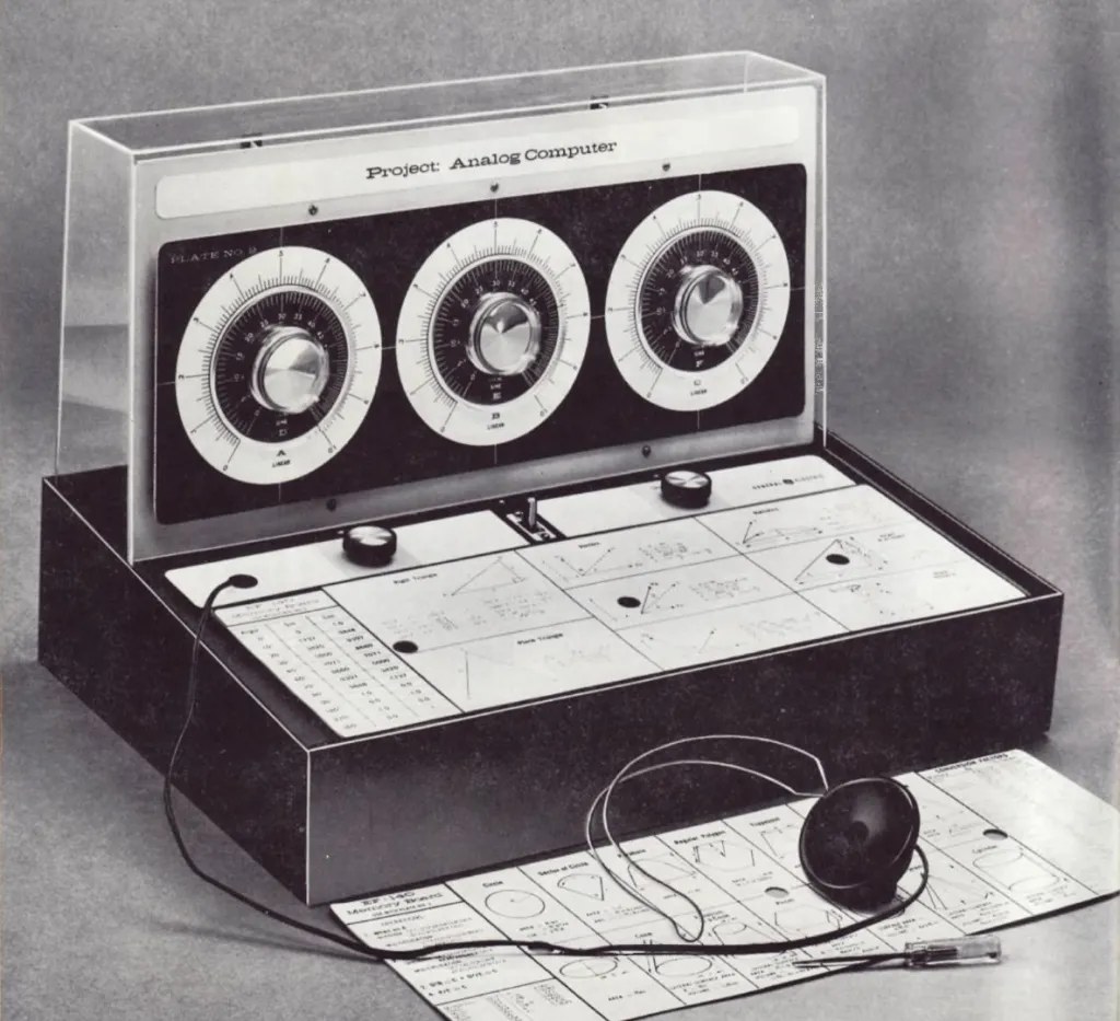
Figure 1 — The finished kit. Three calibrated dials on the vertical board, the tone and calibrate knobs and a memory board on the horizontal panel, and the earphone through which the operator hears the answer. The cabinet is the box the kit arrived in. Photograph: General Electric publicity image; provenance in photo_credits.txt.
1.1 About This Volume
Volume 1 establishes what this machine is, who sold it, to whom, and on what evidence. It also disposes of two pieces of confusion early — the machine’s designation, and the word “computer” in its name — because both mislead a reader who has met the Heathkit EC-1 or the EAI TR-10 first.
The evidential position is unusually simple and unusually good. Almost everything in this series comes from one document: the complete forty-page assembly and instruction manual that General Electric shipped with the kit, copyright 1961, held in this project as a scanned and text-layered PDF. It is a primary source of the best kind — written for the person holding the parts, covering construction, theory, operation and forty-nine worked problems, and ending with a replacement-parts list that doubles as a bill of materials.
What that single source cannot supply is context: what the kit cost, how many were sold, how it was received. Those are marked as unknown wherever they arise.
1.1.1 Depth-Index: The Seven-Volume Series
Table 1 — Depth-Index: The Seven-Volume Series
| Vol | Title | Primary Content |
|---|---|---|
| 1 | Overview & History (this volume) | What GE sold, the EF/EE naming problem, the kit series, the source and its limits, specifications |
| 2 | What the Machine Actually Is | The three-potentiometer ratio bridge, the null detector, the multivibrator, Fig. 30 analysed |
| 3 | Building It | Complete parts list, the hairpin-and-spring connector system, the twenty-two assembly steps, the box-as-cabinet |
| 4 | Operating It | Calibration, scale plates and memory boards, the null technique, the tone control |
| 5 | The Mathematics the Scales Carry | Multiplication, division, powers of ten, logarithms, roots, trigonometric and reciprocal scales |
| 6 | The Problem Set | What GE chose to teach: forty-nine problems from batting averages to the Mercury-Redstone, and what they reveal |
| 7 | Analog Computing Principles | What this machine embodies, what it cannot do, and why that distinction matters |
Note — Cross-references appear as “see Vol N §M.” Each volume is self-contained.
1.2 What It Is
1.2.1 A Science Kit, Not a Laboratory Instrument
The EF-140 is one of a series of educational science kits sold by the General Electric Company through its Educational Science Kit Section at 1001 Broad Street, Utica, New York. It arrives as parts in two transparent “skin packs”, is assembled by the purchaser with the supplied screwdriver and no solder, and is housed in the plastic box it was shipped in.
The manual’s introduction is signed by C. G. Suits, Vice President and Director of Research, General Electric Company, and states the programme’s purpose plainly:
“One may ask why General Electric has undertaken the manufacture of educational kits for Young Americans. The answer is simple. High-quality kits that teach up-to-date science are urgently needed, because they provide a start on understanding the modern world and its technical wonders. Moreover, they may stimulate many bright young people to pursue careers in engineering or science.”
The audience is explicitly the young student at home or in a schoolroom, and the emphasis is explicitly on the transistor: “the electronic kits are built around the transistor, the little semiconductor element that is revolutionizing electronics.”
1.2.2 What the Purchaser Gets
Table 2 — What the Purchaser Gets
| Item | Quantity |
|---|---|
| Mounting boards | 3 (circuit board; vertical dial board; horizontal control panel) |
| Scale plates, each with a memory board on the reverse | 3 |
| Potentiometers | 5 (two 300 Ω w.w.; one 10 kΩ w.w.; one 200 Ω carbon; one 200 kΩ) |
| Transistors | 3 |
| Capacitors | 2 (0.05 µF) |
| Fixed resistors | 6 |
| Earphone | 1 (1 kΩ) |
| Hairpin-and-spring connectors | 15 |
| Brackets | 8 (four Z, two W, one small centre, one large centre) |
| U-nuts | 7 |
| On-off switch, knobs, hardware, pre-cut wire, screwdriver, connector tool | — |
| Batteries | not supplied — four D cells required |
Three transistors, two capacitors, six resistors and five potentiometers. That is the entire active content of the machine, and Vol 2 shows that only three of those parts do any computing at all.
1.2.3 What It Computes
Multiplication, division, powers, roots, logarithms, trigonometric functions of one angle, reciprocals, squares, and any formula assembled from those — to about two significant figures.
The manual is candid about the accuracy, and its candour is one of the better things about it:
“Like other simple analog computers, the one you are about to build gives approximate answers, accurate to two places. However, it was not designed to give exact answers to problems, but to introduce you to the principles of computers and to a new and fascinating field of science and technology.”
What it does not compute is anything involving a rate of change. There is no integrator in it, and Vol 7 treats that fact as the central thing about the machine rather than a footnote.
1.3 Two Points of Confusion
1.3.1 EF-140, Not EE-140
This project’s folder for the machine is named GE_Project_Analog_EE-140, and the machine is sometimes referred to as the EE-140. The manual says EF-140 throughout, and says it in every place a model number appears:
Table 3 — This project's folder for the machine is named GEProjectAnalogEE-140, and the machine is sometimes referred to as the EE-140. The manual says EF-140 throughout, and says it in every place a model number appears
| Location in the manual | Designation |
|---|---|
| Title page | ”Project: Analog Computer — EF-140 — Copyright General Electric Co. 1961” |
| Warranty, Product Service Plan | ”EF-110 EF-120 EF-130 EF-140” |
| Parts Order coupon | ”PARTS ORDER EF-140” |
| Memory board, as printed in the photographs | ”EF-140 Memory Board” |
There is one apparent exception: the warranty coupon in the scanned copy reads “WARRANTY COUPON EF-190”. Since the parts-order coupon on the same page reads EF-140, the warranty text above it lists EF-140, and no EF-190 is mentioned anywhere else, this is best read as an optical-character-recognition artefact or a printing error rather than a second model.
This series uses EF-140. The folder name is retained as-is because it is a stable path that other things point at; renaming it is a separate decision and not this series’ to make.
1.3.2 “Analog Computer” Meant Two Different Things in 1961
A reader who arrives from the Heathkit EC-1 or the EAI TR-10 will expect operational amplifiers, integrators, coefficient potentiometers and a patch panel. The EF-140 has none of those.
It has three potentiometers whose ratios are compared, and an earphone that goes quiet when they balance. It is closer in operating principle to a Wheatstone bridge or a slide rule than to anything in the analog-computing literature.
This is not a criticism and it is not a trick played by General Electric — the manual’s own definition of an analog computer (“they compare physical quantities”) describes the machine accurately. But the two kinds of machine were sold to overlapping audiences in the same years under the same two words, and conflating them makes nonsense of both. Vol 2 establishes what the EF-140 is; Vol 7 treats the distinction directly.
1.4 The Source
1.4.1 The Manual
Project: Analog Computer EF-140, General Electric Company, copyright 1961. Publication number 80-241(1), printed in U.S.A. Forty pages plus an addendum sheet and a replacement-parts page. Held in this project as 1961-general-electric-EF-140.pdf, forty-six scanned pages with an ABBYY FineReader text layer.
Its structure:
Table 4 — Its structure
| Part | Pages | Content |
|---|---|---|
| Front matter | 3 | Index; C. G. Suits introduction; how to use the book |
| Part 1 | 4 | What you will do with this kit — digital versus analog |
| Part 2 | 4–7 | Unpacking; know your components; removing components |
| Part 3 | 8–22 | How to assemble your computer — twenty-two numbered steps |
| Part 4 | 23–24 | How your computer works — the theory, with Figs. 29 and 30 |
| Part 5 | 25–37 | Putting your computer to work — calibration, scales, and forty-nine problems |
| Back matter | 38–40 | Answers; warranty; further reading; other kits |
| Addendum | — | A division-procedure correction and an accuracy adjustment |
The manual credits a named team: “prepared in collaboration with General Electric engineers by the following group of writers and specialists: Leonard Engel, Executive Editor; Dr. Theodore Benjamin, Len Buckwalter, Alex Dorozynski, Barbara Land, Patricia Lauber, Dr. George R. Price and Wallace K. Waterfall.”
1.4.2 How Far It Can Be Trusted
Very far, with one systematic caution.
The manual is a primary source written to be acted on by someone holding the parts. Its parts values, wire lengths, connector numbers and assembly sequence had to be right or the kit would not work, and the replacement-parts list is an independent cross-check on the component list. Its circuit explanation in Part 4 is brief but correct, and it is candid about the machine’s limits.
The caution is the OCR layer. The scan’s text layer contains readings that are certainly wrong, and they are wrong in ways that would matter if quoted:
Table 5 — The caution is the OCR layer. The scan's text layer contains readings that are certainly wrong, and they are wrong in ways that would matter if quoted
| OCR reads | Almost certainly | Why |
|---|---|---|
| ”By 1980, there were more than 10,000 [computers]“ | 1960 | A book copyright 1961 cannot report 1980; the adjacent sentence is “In 1955, there were less than 100" |
| "On May 5, 1981, Commander Alan B. Shepard, Jr., became the first American to pierce the space barrier” | 1961 | Shepard’s flight was 5 May 1961 |
| ”WARRANTY COUPON EF-190” | EF-140 | §3.1 |
| Fractions throughout — “7¾” rendered “73A”, “9½” as “9Vz” | — | The scan mangles vulgar fractions systematically |
The rule applied throughout this series, and it is the same rule this project applies to any scanned source: where a number matters, read the page image rather than the text layer. Every component value, wire length and problem answer quoted in Volumes 2 through 6 was checked against the rendered page.
1.4.3 What Is Not Held
- The price of the kit. Not stated anywhere in the manual. The replacement-parts list gives individual part prices (Vol 3 §5), which bound the parts cost from below but say nothing about the retail price.
- Production quantities, dates of manufacture, or sales figures. Unknown.
- Any GE engineering document — a schematic sheet, a design note, a service bulletin. The manual’s Fig. 30 is the only circuit diagram held.
- Contemporary reviews or reception. None held.
- Photographs of a surviving example. The Wikimedia Commons categories “Electronic Associates” and “Analog computers” were both checked and a keyword search run; neither holds a photograph of an EF-140 or of any other General Electric educational computer kit. The single photograph in this series is GE’s own publicity image.
1.5 The Kit Series
The warranty page names four kits covered by the same Product Service Plan: EF-110, EF-120, EF-130, EF-140. The manual’s closing page advertises the others by name and function:
Table 6 — The warranty page names four kits covered by the same Product Service Plan: EF-110, EF-120, EF-130, EF-140. The manual's closing page advertises the others by name and function
| Kit | Description as advertised |
|---|---|
| Project 1: Transistor Radio | ”Enables construction of a self-contained radio receiver based on the transistor. Receiver has built-in air loop antenna.” |
| Project 2: Transmitter | ”Builds a 3-transistor transmitter. Broadcasts can be received on any closeby standard home radio.” |
| Project 3: Intercom | ”Build and talk over a 3-transistor intercom.” |
| Basic Transistor Lab | ”Builds four types of radio receivers, two tuning systems and two experiments in transistor circuits.” |
| Advanced Electronics Lab | ”Over 50 elementary and advanced experiments in electronics.” |
| Electricity Lab | ”Over 25 fascinating, instructive experiments in electricity and magnetism.” |
The EF-140 is therefore the fourth of a numbered Project series — radio, transmitter, intercom, computer — and the pattern is informative. The first three build a communications device around three transistors. The fourth uses the same three transistors, and the same no-solder connector system, to build something that is presented as a computer. The kit’s design brief was evidently to reach the word “computer” within the parts budget and skill level already established by the series.
Vol 2 shows exactly how that was achieved, and Vol 7 assesses what was given up to achieve it.
1.6 Specifications Quick-Table
Assembled from the manual’s parts list, replacement-parts list, and text. Every value is GE’s.
1.6.1 Computing Elements
Table 7 — Computing Elements
| Element | Designator | Value | Role |
|---|---|---|---|
| Dial X potentiometer | R-9 (or R-11) | 300 Ω wire-wound | first ratio — scale A |
| Dial Y potentiometer | R-10 | 10 kΩ wire-wound | second ratio — scale B |
| Dial Z potentiometer | R-11 (or R-9) | 300 Ω wire-wound | answer ratio — scale C |
Note — The replacement-parts list gives “EK-250 300 ohm VARIABLE RES. (R10, 12)” and “EK-251 10K VARIABLE RESISTOR (R11)”, while the assembly parts table gives “R-9, R-11 300 W.W. POT.” and “R-10 10K W.W. POT.” The two lists disagree on which designator is which. The values agree — two 300 Ω and one 10 kΩ — and the assembly text is unambiguous that the 10 kΩ pot goes in hole [Y]. The designators are not worth reconciling; the hole letters are what matters.
1.6.2 Null Detector and Controls
Table 8 — Null Detector and Controls
| Element | Designator | Value |
|---|---|---|
| Transistors | TR-1, TR-2, TR-3 | green code |
| Capacitors | C-1, C-2 | 0.05 µF |
| Resistors | R-1, R-5 | 1.5 kΩ, ½ W |
| Resistor | R-3 | 10 kΩ, ½ W |
| Resistor | R-4 | 22 kΩ, ½ W |
| Resistors | R-6, R-7 | 33 Ω, ½ W |
| Calibrate potentiometer | R-8 | 200 Ω carbon |
| Tone potentiometer | R-2 | 200 kΩ |
| Earphone | EP-1 | 1 kΩ |
| Switch | SW-1 | SPDT slide, on-off |
Note — The parts table lists “R-6, R-7 33 ⅜ W. RESISTOR” and the assembly text says “the last two resistors, R-6 and R-7 (both 33 ohms; orange-orange-black)”, while the replacement-parts list reads “EK-158 33 ohm Res., 1/2 Watt (R7,8)”. Value and colour code are consistent at 33 Ω; the wattage and the second designator differ between lists. The colour code orange-orange-black confirms 33 Ω.
1.6.3 Power and Physical
Table 9 — Power and Physical
| Parameter | Value |
|---|---|
| Supply | 4 × D cells, purchaser-supplied |
| Construction | no solder; hairpin-and-spring connectors |
| Cabinet | the kit’s own shipping box — clear plastic top, black plastic bottom |
| Scale plates | 3, each with a memory board printed on the reverse |
| Accuracy | approximately two significant figures |
1.6.4 Scale Plates
Table 10 — Scale Plates
| Plate | Scales it carries |
|---|---|
| No. 1 | A, B, C linear; D, E, F logarithmic (powers, roots, logs) |
| No. 2 | A, B, C linear; D, E, F sine and cosine |
| No. 3 | Square and reciprocal scales, for multiple operations without resetting |
Each plate carries the memory board for a different plate on its reverse, so that installing one plate leaves another’s formula sheet face-up on the control panel. That is a genuinely thoughtful piece of design and Vol 4 §4 returns to it.
1.7 What Is Not Known
- Retail price. Not in the manual.
- Production quantity, run dates, or sales. Unknown.
- Whether the EF-140 was revised. The held copy carries an addendum sheet correcting the division procedure and adding a dial-alignment adjustment (Vol 4 §2), which implies at least one round of post-publication correction. Whether the manual or the kit was ever revised beyond that addendum is unknown.
- The transistor type. The parts list says only “GREEN CODE”. No type number is given anywhere, and the manual explicitly tells the builder that either of two physical forms may be supplied and that “the two are electrically identical.”
- Reception. No contemporary review is held.
1.8 Why It Matters
Not for its computing power, which is slight, and not for its influence, which is undocumented. Three other reasons.
It is an exceptionally clear teaching object. Three potentiometers, three transistors and an earphone, all visible, doing something a student can check against arithmetic they already know. The gap between what the machine does physically and what it does mathematically is as small as it is possible to make it. Vol 2 makes that case properly.
It is a document of what “computer” meant to the public in 1961. GE’s Educational Science Kit Section had to decide what a young person should understand by the word, and the manual’s Part 1 — abacus, adding machine, digital versus analog, “By 1960, there were more than 10,000” — is a careful, accurate popular account. The kit is the physical argument attached to it.
It is a useful negative example. Precisely because it carries the name and lacks the apparatus, the EF-140 forces a question that machines like the EC-1 and the TR-10 let a reader skip: what is it that makes something an analog computer? The answer is not “it uses continuous quantities” — the EF-140 does that. Vol 7 works through it.
1.9 What Comes Next
Vol 2 opens the circuit: what the three potentiometers do, why putting two in series multiplies, what the three transistors are actually for, and why there is no amplifier anywhere in the machine. Vol 3 covers construction. Vol 4 covers operation — calibration, the scale plates, and the null technique. Vol 5 takes the mathematics that the printed scales rather than the electronics make possible. Vol 6 works through GE’s forty-nine problems and what they were chosen to teach. Vol 7 places the machine against the operational-amplifier tradition and states what it can and cannot do.
Comments (0)