GE Project EF-140 · Volume 3
GE Project: Analog Computer EF-140 — Volume 3 — Building it
The complete parts list, the no-solder connector system, the twenty-two assembly steps, the wiring schedule, and the shipping carton that becomes the cabinet
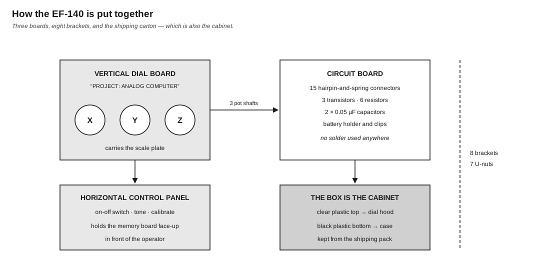
Figure 1 — The mechanical architecture: three boards joined by eight brackets, the whole assembly sliding into the two halves of the packaging. Diagram authored for this dive.
3.1 About this Volume
This volume covers the kit as a physical object: what is in the box, how the parts go together, the wiring schedule, and the design decisions visible in the construction. It is drawn almost entirely from Part 2 and Part 3 of the 1961 manual, with the replacement-parts list as a cross-check.
It is not a restoration guide — no EF-140 was available to this series — but it is detailed enough to tell a person who has one whether it is complete, and to tell a person who is thinking of building a reproduction what they would need.
Cross-references: Vol 1 §5 for the specifications table; Vol 2 for what the parts do; Vol 4 for what to do once it is built.
3.2 What Is In The Box
3.2.1 The Packaging Is Part of the Design
The manual’s very first instruction under “Opening the Kit” is not about parts:
“Hold onto both the clear plastic top and the black plastic bottom of the box. You will need them as part of the cabinet for your computer.”
This is unusual enough to be worth flagging at the outset. The shipping container is not packaging that protects a product; it is part of the product. Section 7 returns to what that decision buys and costs.
Inside, the parts arrive in two transparent “skin packs” — components heat-sealed under film to a backing board — plus three mounting boards, three scale cards and a screwdriver held in the larger pack. The manual’s removal instruction is characteristically direct: “With the screwdriver, cut the plastic film around the components on the skin pack boards… Peel the film to free components. Be careful not to cut any wires or damage components.”
3.2.2 The Components, As the Manual Introduces Them
General Electric’s Part 2 introduces eleven classes of component, and the introductions are aimed at a reader who may not have met any of them. They are worth listing because the list is the parts inventory.
Table 1 — 2.2 The Components, As the Manual Introduces Them
| # | Component | Quantity and detail |
|---|---|---|
| 1 | Mounting boards | 3 — the small white-faced circuit board; the large board labelled “PROJECT: ANALOG COMPUTER” for the three dials; the third with a rectangular hole and the words “TONE” and “CALIBRATE” |
| 2 | Scale plates | 3 — each with a memory board printed on the reverse |
| 3 | Potentiometers | 5 — three with scale knobs for the dials (two marked 300, one marked 10K); two smaller for tone and calibration (marked 200K and 200) |
| 4 | Transistors | 3 |
| 5 | Capacitors | 2 |
| 6 | Resistors | 6 fixed |
| 7 | Earphone | 1 |
| 8 | Tone control | the 200 kΩ pot |
| 9 | Calibration control | the 200 Ω pot |
| 10 | On-off switch | 1 |
| 11 | Hairpin-and-spring connectors | 15 |
Plus: eight brackets, seven U-nuts, screws, speednuts, large nuts, dial knobs, two lengths of insulating sleeving, eighteen pre-cut wires, a connector tool and a screwdriver.
Not supplied: four D cells. “Everything you need to build your computer, including ready-to-use lengths of wire, is packaged in the kit except batteries.”
3.2.3 The Complete Parts Table
From the manual’s own parts list, printed alongside the wiring diagram:
Table 2 — From the manual's own parts list, printed alongside the wiring diagram
| Designator | Description |
|---|---|
| R-1, R-5 | 1.5 kΩ, ½ W resistor |
| R-2 | 200 kΩ pot (tone) |
| R-3 | 10 kΩ, ½ W resistor |
| R-4 | 22 kΩ, ½ W resistor |
| R-6, R-7 | 33 Ω resistor |
| R-8 | 200 Ω carbon pot (calibrate) |
| R-9, R-11 | 300 Ω wire-wound pot |
| R-10 | 10 kΩ wire-wound pot |
| C-1, C-2 | 0.05 µF |
| TR-1, TR-2, TR-3 | transistors, green code |
| EP-1 | 1 kΩ earphone |
| SW-1 | on-off switch |
Note — The designators for the three dial potentiometers differ between the manual’s parts table (R-9 and R-11 at 300 Ω, R-10 at 10 kΩ) and its replacement-parts list (EK-250 “300 ohm variable res. (R10, 12)”, EK-251 “10K variable resistor (R11)”). The values agree across both lists — two 300 Ω and one 10 kΩ — and the assembly text is unambiguous about placement: the 10 kΩ pot goes in hole [Y], the two 300 Ω pots in holes [X] and [Z]. Work from the hole letters, not the R-numbers. Vol 2 §5.2 explains why the odd one out is pot Y.
3.2.4 The Transistor Type Is Not Given
The parts list says “TR 1-2-3 GREEN CODE” and nothing further. No type number appears anywhere in the manual. The manual also warns that the physical package may vary: “It makes no difference which form of transistor you receive in the kit. The two are electrically identical.”
For a reproduction this is the one genuinely unresolved item. The circuit is a low-frequency audio multivibrator and buffer running from about 6 V; almost any small-signal germanium or silicon device of the era would serve, but the original is unidentified and the manual’s lead-identification figure (Fig. No. 11) is the only guide to pinout.
3.3 The No-Solder Connector System
3.3.1 Hairpin and Spring
The kit’s defining construction decision is that nothing is soldered. Fifteen hairpin-and-spring connectors are installed in numbered holes in the circuit board, and every joint is made mechanically.
The manual’s installation method:
“Push the loop of the hairpins up through the bottom of the board… Now place the board on a flat surface, such as a table top. Put a magazine under the board so that the table won’t be scratched. Using the connector tool as in the illustration, and with the small end of the spring down, ram the spring firmly over the pin until it clicks into place.”
And the connection method:
“To insert a wire in a hairpin-and-spring connector, push down the spring and slip the end of the wire through the hairpin loop… Release the spring and the wire will be locked in place. If a wire must be removed, simply push down the spring and pull the wire out.”
A second, related fitting handles the potentiometer and switch terminals: “Use the small black spring to connect a wire to a potentiometer or switch terminal. Slip the spring over the terminal and push it down far enough to expose the small hole at the end of the terminal… Slip the end of the wire through the hole. It will be held tightly when you release the spring.”
3.3.2 Why It Matters
Three consequences, and they shape the whole kit.
It removes the main barrier to entry. A soldering iron is a purchase, a hazard and a skill. Removing it puts the kit within reach of a younger builder working at a kitchen table, which is exactly the audience C. G. Suits’s introduction addresses (Vol 1 §2).
It makes the build reversible. A wire pushed into a spring can be pulled out again. A builder who has made an error loses a minute, not a component — and the manual’s troubleshooting advice (§5.3) depends on being able to undo work.
It is the kit’s likeliest long-term failure mode. Sixty years of spring tension, oxidation on bare copper and dissimilar-metal contact is a lot to ask of a pressure joint. A surviving EF-140 that does not work is more likely to have a high-resistance connector than a failed transistor. The manual anticipates the live version of this problem: “Check also all the wire connections, moving them slightly to make sure that they are tightly held.”
The manual also gives one piece of genuine assembly craft: “If thick and thin wires must be inserted in the same connector, put the thin wire over the thick one to assure good contact.”
3.4 Assembly
3.4.1 The Sequence
The manual’s Part 3 runs to twenty-two numbered steps across fifteen pages. Condensed:
Table 3 — The manual's Part 3 runs to twenty-two numbered steps across fifteen pages. Condensed
| Steps | What happens |
|---|---|
| 1 | Install the fifteen hairpin-and-spring connectors in the circuit board |
| 2 | Mount the battery clips and holder — positive clip identified by “a dotted pattern on one end” |
| 3 | Mount the three dial potentiometers: 300 Ω in [X], 10 kΩ in [Y], 300 Ω in [Z] |
| 4 | Wire the circuit board — eighteen pre-cut wires |
| 5 | Install TR-1 and TR-2 |
| 6 | Install R-1, R-3, R-4, R-5 |
| 7 | Install C-1 and C-2, with insulating sleeving where leads cross |
| 8 | Install TR-3 |
| 9 | Install the on-off switch in the TONE/CALIBRATE board |
| 10–17 | Fit brackets and U-nuts; mount the tone and calibrate pots; join the three boards |
| 18 | Complete the wiring between boards — six previously free wire ends, plus R-6 and R-7 |
| 19 | Connect the earphone |
| 20 | Install the four D cells |
| 21 | Test |
| 22 | Install the assembly in the cabinet |
3.4.2 Two Warnings the Manual Repeats
Battery polarity. “Be sure to put the nut on so that its corners can bite into the board” for the clips, and at step 20: “Take care to install them correctly. Incorrect mounting can damage components like the transistors as well as prevent the computer from working.” With germanium transistors and no reverse protection, this is a real hazard rather than boilerplate.
Transistor lead identification. “Note carefully which wire on each transistor is the base, which the collector and which the emitter. Be sure to attach each to the proper connector. Getting it wrong can damage the transistor as well as prevent your computer from working. Also use special care in bending the ends of the transistor leads when you connect them. Avoid bending them back and forth.”
3.4.3 Transistor Connections
Table 4 — 4.3 Transistor Connections
| Transistor | Base | Collector | Emitter |
|---|---|---|---|
| TR-1 | connector [8] | connector [5] | connector [15] |
| TR-2 | connector [9] | connector [6] | connector [14] |
| TR-3 | connector [10] | connector [7] | connector [13] |
3.4.4 Resistor and Capacitor Connections
Table 5 — 4.4 Resistor and Capacitor Connections
| Part | Value | Between |
|---|---|---|
| R-1 | 1.5 kΩ | [1] and [5] |
| R-3 | 10 kΩ | [4] and [8] |
| R-4 | 22 kΩ | [2] and [9] |
| R-5 | 1.5 kΩ | [2] and [6] |
| C-1 | 0.05 µF | [5] and [9] |
| C-2 | 0.05 µF | [8] and [6] |
| R-6, R-7 | 33 Ω | across the calibrate pot: terminal 1–2 and terminal 2–3 |
The cross-coupling is visible in that table: R-1 and C-1 tie TR-1’s collector to TR-2’s base side, R-5 and C-2 tie the other way. That symmetry is the multivibrator (Vol 2 §7.1).
The manual notes a practical point about the capacitors: “notice that two of the capacitor leads will cross. To avoid a short circuit, slip a piece of plastic insulating ‘spaghetti’ over each of these wires before they are inserted in the connectors. Two pieces of plastic spaghetti are provided in the kit for this purpose.”
The colour codes given for identification: R-1 and R-5, brown-green-red; R-3, brown-black-orange; R-4, red-red-orange; R-6 and R-7, orange-orange-black.
3.5 The Wiring Schedule
Eighteen wires, pre-cut and pre-stripped, colour-coded for identification. The manual gives them as a table alongside the wiring diagram:
Table 6 — Eighteen wires, pre-cut and pre-stripped, colour-coded for identification. The manual gives them as a table alongside the wiring diagram
| # | Length | Colour | From | Via holes | To |
|---|---|---|---|---|---|
| 1 | 7¾″ | black | terminal 1 of Z | — | terminal 1 of Y |
| 2 | 7¾″ | black | terminal 1 of Y | — | terminal 1 of X |
| 3 | 11¾″ | black | connector [4] | G-M-L | tone pot |
| 4 | 6″ | red | tone pot | — | terminal 2 of switch |
| 5 | 7″ | red | battery − | S-R | terminal 1 of switch |
| 6 | 7¾″ | red | terminal 3 of Y | — | terminal 2 of X |
| 7 | 9½″ | red | connector [1] | F-Q-P | terminal 2 of switch |
| 8 | 10″ | brown | terminal 2 of Y | C-H | connector [11] |
| 9 | 14¼″ | brown | terminal 2 of Z | A-J | connector [12] |
| 10 | 13¼″ | orange | connector [13] | N-U-W | terminal 2 of calibrate pot |
| 11 | 12¼″ | blue | terminal 3 of Z | B-Y-X | terminal 3 of calibrate pot |
| 12 | 17¼″ | blue | terminal 3 of X | E-T-U | terminal 1 of calibrate pot |
| 13 | 5¼″ | yellow | battery + | O | connector [14] |
| 14 | 9¼″ | yellow | terminal 1 of X | D | battery + |
| 15 | 2″ | bare | connector [7] | — | connector [3] |
| 16 | 2½″ | bare | connector [6] | — | connector [10] |
| 17 | 3½″ | bare | connector [14] | — | connector [15] |
| 18 | 6½″ | bare | connector [1] | via [2] | connector [3] |
Note — The printed table abbreviates the tone and calibrate pots as “T” and “B” and gives wire 3’s destination as “TER. 3 of T”, while the step-18 narrative says the black wire from connector [4] attaches “to terminal 2 of the 200K pot, the tone control.” Where the table and the narrative differ, the narrative is the more reliable, since it is the text a builder follows step by step. The scan’s fractions are also unreliable in the text layer (Vol 1 §4.2); the lengths above were read from the page image.
Wires 1, 2, 6 and 14 are the computing circuit — they connect the three dial potentiometers to each other and to the supply. That is four wires out of eighteen. The remaining fourteen serve the detector, the controls and the battery.
3.6 The Cabinet
3.6.1 The Box
Step 22:
“Everything worked well? You are ready to install your computer in a handsome console fashioned from the clear and black plastic halves of the box your kit came packed in. Set the black plastic bottom of the box before you. Stand the clear top, open side facing you, at the back inside the bottom of the box. Lift the computer assembly and slide it back into the cabinet… The vertical dial board should fit, facing you, into the opening of the clear top. The horizontal board should rest on the brackets in the bottom of the cabinet.”
The clear top becomes the hood over the dials; the black bottom becomes the case. Two Z-brackets fitted to the bottom of the box in step 17 receive the horizontal board, and screws from outside the case secure the whole assembly.
3.6.2 What the Decision Buys
Cost. A moulded cabinet is one of the more expensive parts of a consumer kit. Eliminating it entirely, by giving the packaging a second job, removes that cost without removing the cabinet.
Presentation. The finished object looks like an instrument rather than like a school project — the clear hood over three large calibrated dials is the whole visual identity of the machine (Fig. 1 of Vol 1).
A closing gesture. The final act of assembly transforms the container into the product. For a kit whose purpose is to make a young person feel they have built something real, that is a well-judged piece of design.
3.6.3 What It Costs
Survivability. Thin vacuum-formed plastic sixty years old is brittle, scratched and frequently discarded. An EF-140 that has lost its box has lost its cabinet, and no replacement exists.
Rigidity. The manual’s own assembly notes hint at the tolerances: “If the holes do not quite correspond, move the vertical board right and left until the holes are aligned”, and “use the switch to move the horizontal board until they are lined up.” The structure is adjusted into alignment rather than located by it.
3.7 Test and Troubleshooting
3.7.1 The Manual’s Test
Step 21, before the cabinet goes on:
“To make sure that the set is properly wired, put on the earphone and turn the switch to the on position. You should hear a tone. Turn the knob on the calibration potentiometer, and the tone should increase and decrease in volume. Turn the knob of the tone control and the pitch of the tone should change. Turn the pot knobs of potentiometers X, Y and Z, and the volume of the tone should again increase or decrease.”
This is a well-designed test. It checks, in four actions: that the multivibrator runs and the earphone works; that the calibrate network affects the balance; that the tone control affects frequency and not amplitude; and that all three computing pots are in the bridge. A machine passing all four is wired correctly in every respect that matters.
3.7.2 If It Fails
“Otherwise, go over what you have done step by step, checking each of the connections and components for proper wiring. Check also all the wire connections, moving them slightly to make sure that they are tightly held. Check the distribution of the transistor leads.”
The lead-checking advice is worth repeating because it is non-obvious and avoids dismantling: “You can verify the position of the leads without removing the transistors, by looking at the points of origin of each lead and making a brief diagram for each one of them. Then compare this diagram to the one in Fig. No. 11.”
3.7.3 A Modern Diagnostic Order
This series’ suggestion, for a surviving machine, in increasing order of effort:
Table 7 — 7.3 A Modern Diagnostic Order
| Step | Check | Why first |
|---|---|---|
| 1 | Battery voltage and clip contact | sixty-year-old clips corrode; the commonest fault by far |
| 2 | Every spring connector, by wiggling under tension | pressure joints degrade (§3.2) |
| 3 | Tone present at all? | separates detector faults from bridge faults immediately |
| 4 | Tone changes with the tone knob? | confirms the multivibrator and R-2 |
| 5 | Tone changes with each of X, Y, Z? | a dial that does nothing isolates one branch of the bridge |
| 6 | Can it be calibrated at .6 × .7 = .42? | Vol 4 §2; failure here with all of 1–5 passing points at R-6/R-7 or the calibrate pot |
| 7 | Only then, transistors and capacitors | least likely, most disruptive to test |
3.8 Replacement Parts and What They Cost
The manual’s replacement-parts page is the only pricing information in any source held for this machine. It prices parts, not the kit (Vol 1 §7), but it is a useful inventory and a rough guide to relative value.
Table 8 — Replacement Parts and What They Cost
| Catalogue no. | Description | Price |
|---|---|---|
| EK-104 | Knob, tone & calibrate | $0.25 |
| EK-111 | Positive battery contact | $0.25 |
| EK-112 | Negative battery contact | $0.25 |
| EK-113 | Spring connector assembly (5) | $0.25 |
| EK-115 | Spring, for switch (5) | $0.25 |
| EK-116 | Screwdriver | $0.25 |
| EK-117 | Earphone | $2.50 |
| EK-121 | Screw, sheet metal (7) | $0.25 |
| EK-122 | Fastener, speed nut (5) | $0.25 |
| EK-129 | Hookup wire (3 feet) | $0.25 |
| EK-134 | 10 kΩ resistor, ½ W (R-3) | $0.25 |
| EK-135 | SPDT slide switch (SW-1) | $0.50 |
| EK-136 | Transistor (TR-1, 2, 3) | $1.75 |
| EK-140 | Battery holder | $0.25 |
| EK-147 | Connector tool | $0.25 |
| EK-149 | 0.05 µF capacitor (C-1, 2) | $0.25 |
| EK-156 | 22 kΩ resistor, ½ W (R-4) | $0.25 |
| EK-158 | 33 Ω resistor, ½ W | $0.25 |
| EK-175 | 1.5 kΩ resistor, ½ W (R-1, 5) | $0.25 |
| EK-216 | Cabinet top | $1.50 |
| EK-217 | Cabinet bottom | $2.25 |
| EK-218 | Cabinet clip | $0.25 |
| EK-220 | Earphone headband | $0.50 |
| EK-233 | Knob, dial | $0.50 |
| EK-234 | Circuit board | $0.50 |
| EK-235 | Vertical control panel | $1.00 |
| EK-236 | Horizontal control panel | $1.00 |
| EK-237 | Centre bracket, control panels to cabinet bottom | $0.25 |
| EK-238 | Spacer bracket, circuit board to vertical panel | $0.25 |
| EK-239 | Support bracket, control panels to cabinet | $0.25 |
| EK-240 | Chassis mounting bracket | $0.45 |
| EK-242 | Hex nut (pkg. 5) | $0.25 |
| EK-243 | ⅜″ U-clip (pkg. 5) | $0.25 |
| EK-244 | Plate #1, log scale, with memory board | $0.75 |
| EK-245 | Plate #2, sin/cos scale, with memory board | $0.75 |
| EK-246 | Plate #3, square-reciprocal scale, with memory board | $0.75 |
| EK-248 | 200 kΩ variable resistor (R-2) | $0.75 |
| EK-249 | 200 Ω variable resistor (R-9) | $0.75 |
| EK-250 | 300 Ω variable resistor | $1.25 |
| EK-251 | 10 kΩ variable resistor | $1.25 |
“The above prices include the standard fee for handling costs.”
3.8.1 What the Prices Reveal
Two observations.
The cabinet halves are among the most expensive items on the list — $1.50 and $2.25, more than any resistor, capacitor or transistor, and together more than the three transistors. That is the strongest available confirmation that using the packaging as the cabinet (§6.2) was a cost decision and a significant one.
The three computing potentiometers cost $1.25 each, against $0.75 for the tone and calibrate pots. The wire-wound calibrated units are the machine’s precision parts and are priced accordingly. Vol 2 §5 explains why their values were chosen; this list shows they were also its most expensive electrical components.
3.8.2 Service Terms
For completeness: the warranty ran 90 days from purchase and covered defective material and workmanship, not user damage. A fully assembled non-working kit could be returned to General Electric Company, Educational Science Kit Section, Product Service, 1001 Broad Street, Utica, New York, pre-paid by Railway Express with a two-dollar handling fee. Replacement parts were ordered from General Electric Company, P.O. Box 831, Utica, New York — “On orders for less than one dollar ($1.00), coins will be accepted.”
The manual also offers a distinctly period piece of advice before returning anything: “you may wish to consult with a science teacher at your high school or other qualified local person.”
3.9 What Comes Next
Vol 4 covers operation: calibrating the machine at a multiplication whose answer is already known, installing scale plates, and the practical business of finding a null by ear. Vol 5 turns to the printed scales.
Comments (0)