GE Project EF-140 · Volume 2
GE Project: Analog Computer EF-140 — Volume 2 — What the machine actually is
Three potentiometers, a bridge, and an audible null — the circuit analysed from Fig. No. 30, including the loading question the manual never raises
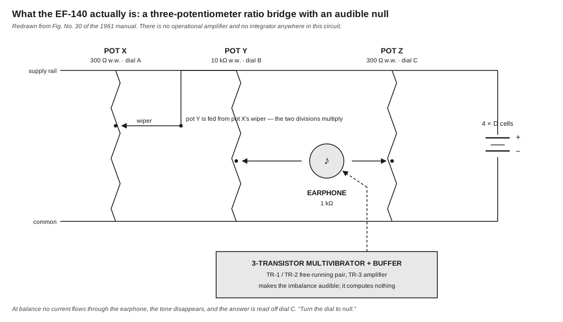
Figure 1 — The EF-140 circuit, redrawn from Fig. No. 30 of the 1961 manual with component values from the manual’s parts table. There is no operational amplifier and no integrator anywhere in it. Diagram authored for this dive.
2.1 About this Volume
This volume takes the machine apart electrically. It establishes what the three computing potentiometers do, why connecting two of them in series performs a multiplication, what the null condition means, what the three transistors are actually for, and what is conspicuously absent.
The manual’s own explanation occupies two pages and is correct as far as it goes. This volume goes further in two places — the loading question of §5 and the null-immunity argument of §6 — and both are marked as this series’ analysis rather than General Electric’s.
Cross-references: Vol 1 §3.2 for why the machine’s name misleads; Vol 3 for construction; Vol 4 for the operating procedure that follows from this circuit; Vol 7 for what the circuit implies about the machine’s class.
2.2 The Manual’s Own Account
General Electric’s Part 4, “How Your Computer Works”, is short enough to quote at its core, and it is worth reading before any analysis because it is accurate:
“What happens is this: An electric current is divided into two parts. One part is for the problem. The other represents the answer. The problem part is put through steps corresponding to the multiplications and other mathematical operations called for in the problem. The answer current is then adjusted to match the problem current. The value of the adjusted current gives the answer. It can be read off on a scale.”
And on the division of the machine:
“First of all, your computer has two basic sections. The three pots X, Y and Z form one. It has to do with the computation. Most of the rest of the computer forms the other section. The latter has to do with reading answers more accurately and easily.”
That second passage is the key to the whole machine, and it deserves emphasis because it is easy to read past. Three potentiometers do all of the computing. Everything else — three transistors, two capacitors, six resistors, the earphone — exists only to tell the operator when the computation has balanced.
2.3 The Potentiometer as a Ratio Element
2.3.1 What the Manual Says
The manual’s Fig. No. 29 shows a potentiometer as an arc of resistance wire from A to C with a movable arm B, and explains:
“A thin high-resistance wire is wound around the arc from A to C, and the arm B can swing around the arc from A to C. When the arm is all the way to the right, there is very little resistance between A and B. As a result, there is maximum current flow and little loss of voltage. As the arm is moved away from A, the current must pass through more and more of the wire, the resistance increases, the voltage drops and less current flows through.”
2.3.2 What Matters Computationally
Stated in modern terms: a potentiometer connected across a voltage E delivers at its wiper a voltage kE, where k is the fraction of the winding between the wiper and the grounded end, and k lies between 0 and 1.
Three properties make this useful as a computing element:
Table 1 — Three properties make this useful as a computing element
| Property | Consequence |
|---|---|
| k depends on position, not on resistance value | the dial reading is the number; the ohms are irrelevant |
| k is bounded to [0, 1] | every quantity must be scaled into that range — hence the powers-of-ten discipline of Vol 5 |
| k is set by hand and read from a printed scale | the scale decides what mathematical function the dial performs |
The third is the machine’s whole design. A linear scale makes the dial read k directly and the machine multiplies. A logarithmic scale makes the same dial, at the same physical position, read a different number — and the same circuit now handles powers and roots. Nothing electrical changes. Vol 5 develops this.
2.4 Why Two Dials in Series Multiply
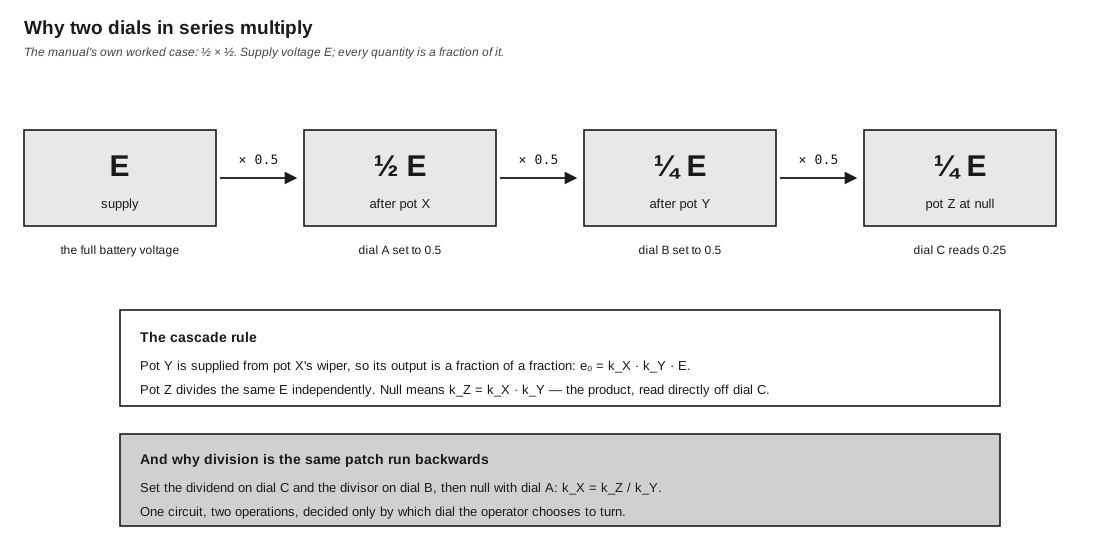
Figure 2 — The cascade, worked for the manual’s own example of ½ × ½. Diagram authored for this dive.
2.4.1 The Topology
From the manual’s Fig. No. 30 and its accompanying text:
“Notice first that part of the current from the batteries goes to pot X and then to pot Y, while the other part goes to pot Z.”
So the supply feeds two parallel branches:
- the problem branch — pot X across the supply, with pot Y hanging from X’s wiper;
- the answer branch — pot Z across the supply.
The earphone bridges pot Y’s wiper to pot Z’s wiper. This is a bridge, in the Wheatstone sense: two dividers compared by a detector across their outputs.
2.4.2 The Manual’s Worked Case
“The arm of pot X is set so that the current to pot Y must first flow through half the resistance wire in pot X. This reduces the voltage supplied to pot Y — which receives current only through pot X — by half. But pot Y is also set so that the current must flow through half the resistance wire. So the voltage is halved again. Half of a half is one-quarter. In effect, you have multiplied ½ by ½.”
2.4.3 The General Rule
Because pot Y is supplied from pot X’s wiper rather than from the battery, Y divides a voltage that has already been divided:
e_Y = k_Y · (k_X · E) = k_X · k_Y · EThe wiper of Y therefore carries the product of the two dial settings, as a fraction of the supply. Meanwhile pot Z divides the supply independently:
e_Z = k_Z · ENull — no current through the earphone — requires e_Y = e_Z, hence
k_Z = k_X · k_YThe supply voltage E cancels completely. This is the reason the machine needs no voltage regulation and no reference: the answer is a ratio of ratios, and the battery’s absolute voltage never enters it. Four D cells that have dropped from 6.0 V to 5.2 V give the same answer, more quietly.
2.4.4 Division Is the Same Circuit
Nothing in §4.3 privileges any particular dial. The relation k_Z = k_X · k_Y can be solved for whichever quantity is unknown, and “unknown” simply means “the dial the operator turns to reach null.”
Table 2 — 4.4 Division Is the Same Circuit
| Operation | Set | Null with | Read | Relation |
|---|---|---|---|---|
| Multiplication | X (scale A), Y (scale B) | Z | Z on scale C | k_Z = k_X · k_Y |
| Division | Z (scale C), Y (scale B) | X | X on scale A | k_X = k_Z / k_Y |
| Division | Z (scale C), X (scale A) | Y | Y on scale B | k_Y = k_Z / k_X |
The manual states this directly: “the number to be divided (the dividend) is set on scale C and the dividing number (the divisor) on scale B, and your answer (the quotient) is read on scale A… But dial Z must always be used for the number being divided.”
One machine, one circuit, two operations — distinguished only by which knob the operator chooses to move. Vol 4 §5 covers the practical consequence, which is that division sometimes cannot reach null without rescaling.
2.5 The Loading Question
This section is this series’ analysis. The manual does not raise the issue.
2.5.1 The Problem
The derivation in §4.3 treats pot X as an ideal voltage source at k_X·E. It is not. A real potentiometer has output resistance, and pot Y draws current from it. If that current is significant, the voltage at X’s wiper sags below k_X·E and the product comes out low.
At its worst — the wiper at mid-travel — pot X’s output resistance is the two halves of its winding in parallel:
R_out = (R_X/2) ∥ (R_X/2) = R_X/4With R_X = 300 Ω, that is 75 Ω.
2.5.2 Why the Values Are What They Are
The load is pot Y, and the manual specifies pot Y as 10 kΩ while pots X and Z are 300 Ω. The fractional loading error is approximately
R_out / R_Y = 75 Ω / 10,000 Ω ≈ 0.0075 = 0.75 %Well under one percent — comfortably inside the “accurate to two places” the manual claims, and therefore invisible to the operator.
This answers a question the parts list otherwise leaves hanging: why is one of the three computing potentiometers a different value from the other two? Not for any reason to do with the mathematics, which is scale-free. Pot Y is thirty-three times higher in resistance precisely so that it does not load pot X enough to spoil the product. The two 300 Ω units are X and Z — the two that are driven directly from the battery and compared against each other.
It is a small piece of engineering that the manual never mentions and that a builder substituting “any three pots” would destroy.
2.5.3 A Caution About Substitution
A restorer replacing a failed potentiometer should keep the values as specified. Fitting three identical 300 Ω units would introduce a loading error of roughly
75 Ω / 300 Ω ≈ 25 %at mid-travel — the machine would still null, but the answers would be substantially and non-linearly wrong. Fitting three identical 10 kΩ units would preserve accuracy but increase the battery drain path resistance and change the tone circuit’s behaviour.
2.6 The Null, and Why It Is the Right Technique
2.6.1 What Null Means Here
At balance, the two wipers sit at the same potential, no current flows through the earphone, and the tone stops. The manual’s phrase is exact: “In the language of science, you ‘turn the dial to null.‘“
2.6.2 The Detector Cannot Corrupt the Answer
This section is this series’ analysis.
A detector that draws current normally disturbs what it measures. A null detector does not — because at the moment of measurement it is carrying no current.
The earphone is a 1 kΩ load bridging two dividers whose output resistances are on the order of 75 Ω. Away from balance, that is a substantial load and it does distort both branches. But the operator does not read anything away from balance; the only reading taken is at the null, and at the null the earphone carries zero current, drops no voltage, and therefore imposes no load on either branch at all.
The consequence is worth stating plainly: the earphone’s impedance does not appear in the answer. Neither does the transistor circuit driving it, nor the battery voltage (§4.3), nor the absolute resistance of any of the three pots. The answer depends only on three mechanical dial positions.
That is why a kit built with no solder, powered by flashlight batteries and read by ear can hold two significant figures at all. It is the same reason a Wheatstone bridge outperforms the galvanometer in it, and it is the single most transferable idea in the machine.
2.6.3 Why Silence Rather Than a Meter
A meter would have worked, and the manual says so: “An analog computer could be built with nothing but three pots and a voltmeter or other device to tell when the currents from pot Y and pot Z were of equal voltage. Your computer, however, has a more sensitive, easier-to-use arrangement.”
Three reasons the earphone is the better choice for this kit:
- Cost and robustness. A 1 kΩ earphone is cheaper and far harder to damage than a sensitive DC meter movement, and it needs no zeroing.
- Sensitivity near zero. Human hearing resolves small changes in a quiet tone well, and the ear’s response is roughly logarithmic — it discriminates most finely exactly where the signal is small, which is where the null is.
- It frees the eyes. The operator watches the dial while listening for the null. With a meter, the eyes must move between meter and scale, which is precisely when a ten-turn dial gets over-shot.
The cost is that a DC bridge produces no tone at all in an earphone — which is what the transistors are for.
2.7 What the Three Transistors Do
2.7.1 Not Computing
The manual is clear that the oscillator is a convenience, not a computing element:
“The current to the pots is fed through a pair of transistors wired up in what computer men call a ‘flip-flop’ and radio men term a multivibrator. When the on-off switch is first turned on, the current to one transistor is larger than the current to the other. This starts a current see-sawing back and forth between the two transistors. The see-saw current will continue as long as the currents from the pots are out of balance.”
And on the third:
“the flip-flop is arranged so that the see-saw current surges back and forth many hundreds of times a second. Further, the see-saw current is amplified or made stronger by a third transistor, and is then fed into an earphone. In the earphone, it causes a diaphragm to vibrate and generate a tone which you can hear.”
Table 3 — 7.1 Not Computing
| Transistor | Role |
|---|---|
| TR-1, TR-2 | free-running multivibrator pair — converts the DC imbalance into an audio-frequency signal |
| TR-3 | amplifier — drives the 1 kΩ earphone |
The supporting parts follow: C-1 and C-2 (0.05 µF) are the cross-coupling capacitors that set the multivibrator’s frequency; R-1, R-3, R-4 and R-5 bias the pair; R-2 (200 kΩ) is the tone control, adjusting the pitch; R-8 (200 Ω) with R-6 and R-7 (33 Ω) forms the calibrate network.
2.7.2 The Honest Summary
Six of the eleven distinct electrical parts in this machine, and all three of its semiconductors, exist to make a needle-less detector audible. Not one of them touches the number being computed. A reader who learns that the EF-140 “uses three transistors” and infers that the transistors are amplifying, summing or integrating something has inferred wrongly.
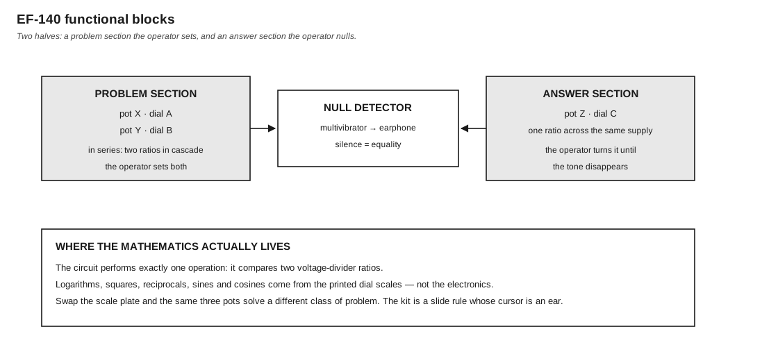
Figure 3 — The functional division. Diagram authored for this dive.
2.8 What Is Absent
Set against the operational-amplifier machines of the same period — the Heathkit EC-1 of 1959, the EAI PACE TR-10 — the EF-140 lacks the following, entirely rather than in reduced form:
Table 4 — Set against the operational-amplifier machines of the same period — the Heathkit EC-1 of 1959, the EAI PACE TR-10 — the EF-140 lacks the following, entirely rather than in reduced form
| Absent | Consequence |
|---|---|
| Any amplifier in the signal path | no gain; every computed quantity is smaller than the supply |
| Any integrator | no rate, no time, no differential equation — ever |
| Any feedback loop | no inversion of a function, no implicit solution |
| A summing junction | the machine cannot add; multiplication and division only |
| A patch panel | the interconnection is fixed at assembly and never changes |
| A reference supply | unnecessary, since the answer is a ratio (§4.3) |
| A continuous-time output | there is one steady answer, read at balance; nothing is plotted |
The last two are strengths rather than deficiencies, and the first four are why Vol 7 argues that the machine belongs to a different tradition rather than to a junior position in this one.
The absence of addition deserves a note, because it is easy to miss. The machine multiplies and divides, and the memory boards supply formulas of the forms XY = Z and A/B = C — both multiplicative. Sums are handled by the operator, on paper, between machine operations. The manual’s Problem 12 (“Compare the volume of Cheops’ pyramid with the volume of the Empire State Building”) and the ballistic problems of Vol 6 §6 all involve arithmetic done by hand around the machine’s multiplications.
2.9 Accuracy
2.9.1 The Claim
“Accurate to two places,” stated twice in the manual.
2.9.2 Where the Limit Comes From
Ranked by contribution, this series’ assessment:
Table 5 — Ranked by contribution, this series' assessment
| Source | Magnitude | Note |
|---|---|---|
| Reading the dial | dominant | a printed scale and a hairline, read by eye; the practical limit |
| Finding the null by ear | significant | how precisely silence can be located, and it degrades as the tone weakens |
| Dial-to-winding alignment | significant | the manual’s own addendum gives a procedure to improve it (Vol 4 §6) |
| Loading of X by Y | ~0.75 % worst case | §5.2 |
| Potentiometer linearity | unstated | wire-wound; GE gives no figure |
| Battery voltage | none | cancels (§4.3) |
| Earphone impedance | none | at null, no current flows (§6.2) |
| Temperature | negligible | affects all branches nearly equally |
The interesting feature of that table is how much of it is zero. The machine’s electrical error sources are almost all eliminated by the ratio-and-null architecture; what limits it is a human reading a printed scale. Two significant figures is exactly what one would expect of a dial of that size, and it is the same limit that governs a slide rule.
2.9.3 Improving It
The manual’s addendum offers one adjustment — squaring the dials to their potentiometers’ true zero (Vol 4 §6). Beyond that, the honest answer is that the limit is the scale, not the circuit, and a larger dial with a finer scale would improve the machine more than any electrical change.
2.10 Summary
Table 6 — Summary
| Question | Answer |
|---|---|
| What computes? | Three potentiometers, X, Y and Z |
| How does it multiply? | X and Y in cascade; the wiper of Y carries k_X·k_Y·E |
| How is the answer read? | Pot Z is turned until the earphone falls silent; k_Z = k_X·k_Y |
| Why does the battery voltage not matter? | It cancels — the answer is a ratio of ratios |
| Why is pot Y 10 kΩ when X and Z are 300 Ω? | So it does not load pot X; ~0.75 % worst case (§5.2) |
| What do the transistors do? | Make the imbalance audible. They compute nothing. |
| What limits accuracy? | Reading a printed dial by eye — about two significant figures |
| Can it solve a differential equation? | No. There is no integrator, and no way to make one. |
2.11 What Comes Next
Vol 3 covers construction: the complete parts list, the no-solder connector system, the twenty-two assembly steps and the shipping box that becomes the cabinet. Vol 4 covers operation — calibration, the scale plates, and the null technique in practice. Vol 5 turns to the printed scales, which is where the machine’s mathematical range actually lives.
Comments (0)