EAI PACE TR-10 · Volume 6
EAI PACE TR-10 — Volume 6 — Specifications & the documentary record
Specification GPAC-TR-10 PS 6305 clause by clause against the brochure, every divergence catalogued, and an honest list of what nobody here can source
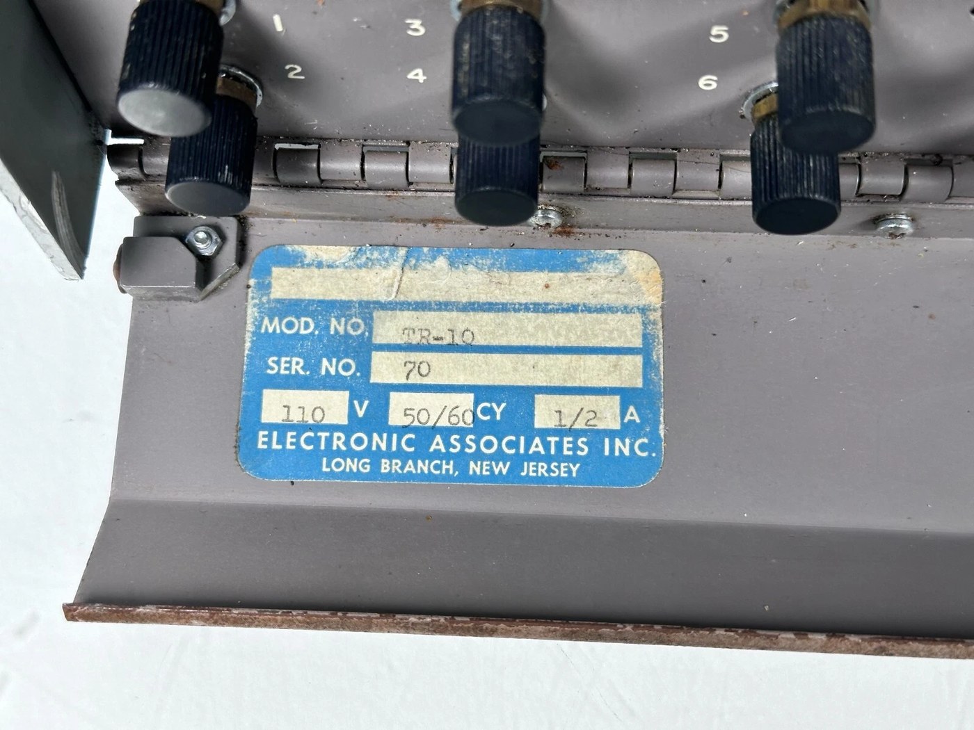
Figure 1 — The data plate of the console photographed for this series: model TR-10, serial no. 70, 110 V, 50/60 cycles, ½ A. The input voltage stamped here differs from both the brochure’s 115 V and the specification’s 100–125 V range — a small illustration of this volume’s subject. Photograph: locally held collector image.
6.1 About this Volume
Volumes 2 through 5 drew on two documents that do not agree with each other. This volume sets them side by side.
It prints specification GPAC-TR-10 PS 6305 clause by clause, states what the brochure says on the same point, and gives a verdict on each divergence. It then catalogues the brochure’s contradictions with itself, separates engineering claims from sales copy, and closes with what is simply not known and what document would settle it.
The purpose is not pedantry. A reader who takes a figure from this series into a restoration, a simulation or a citation needs to know whether it is a requirement, a product claim, a measurement, or an inference — and these four are mixed together in almost every published account of this machine.
Cross-references: Vol 1 §3 introduced the sources; every technical volume points here.
6.2 The Two Documents
6.2.1 What a Procurement Specification Is
Specifications for General Purpose Desk-Top Analog Computer (TR-10), document number GPAC-TR-10 PS 6305, Electronic Associates, Inc., Long Branch, N.J. Seven pages, eleven numbered sections, every requirement phrased “shall”.
A procurement specification states what a supplier undertakes to deliver. Read correctly it is the most reliable source for limits — a clause reading “drift of a gain one integrator shall not exceed 50 microvolts per second maximum” is a commitment that can be tested against, and a machine failing it would have been rejected.
Read incorrectly it becomes the least reliable source for description. Nothing in it is an observation. Section 1.1 opens with “Reliability, accuracy and operating convenience shall be paramount considerations in the design of the equipment” — an aspiration, not a fact about hardware. And a requirements document may describe a machine that was never built exactly that way, which §5.3 below shows happened here.
6.2.2 What a Sales Brochure Is
PACE TR-10 Analog Computer, EAI Bulletin No. AC 934–… (the number is truncated at the edge of the scan held here). Sixteen pages, colour, extensive photography.
Its value is that it describes shipped product: module type numbers, row capacities, position rules, the exact contents of two named configurations, patch-cord part numbers and lengths. That information could only come from a product that existed, and it is far richer than the specification on everything to do with configuration.
Its weakness is that it is selling. Superlatives, round numbers and comparative claims in it are marketing until corroborated, and it contradicts itself in at least three places (§6).
6.2.3 The Rule Applied Throughout This Series
Table 1 — 2.3 The Rule Applied Throughout This Series
| Question type | Prefer | Because |
|---|---|---|
| A performance limit | the specification | that is what it exists to state |
| A configuration or type number | the brochure | it describes what shipped |
| A physical dimension of the delivered machine | the brochure | the specification gives an envelope, not a measurement |
| Anything about a specific surviving machine | the photographs | neither document describes an individual console |
| A superlative or market claim | neither | treat as vendor copy (§7) |
6.3 The Specification, Clause by Clause
6.3.1 Section 1 — General Description
Table 2 — 3.1 Section 1 — General Description
| Clause | Requirement |
|---|---|
| 1.1 | Completely transistorised for reliability, stability and compactness. Fully expanded: ≤ 100 lb, no greater than 16″ W × 23″ H × 16″ D |
| 1.3 | Up to twenty operational amplifiers |
| 1.4 | Up to twenty-four precision potentiometers |
| 1.5 | Up to nine multipliers |
| 1.6 | Up to eighteen unipolar X² DFG |
| 1.7 | One comparator, if required |
| 1.8 | Up to two function switches |
| 1.9–1.11 | One reference supply, one power supply, patching elements |
Note — Clause 1.6’s “up to eighteen unipolar X² DFG” sits awkwardly against §2.1.3’s “up to nine X² diode function generators” in the same document. The reconciliation is that the 16.101 is a dual chassis: nine dual units provide eighteen unipolar generators. The two clauses count different things.
6.3.2 Section 2 — Computer and Control Panel
Table 3 — 3.2 Section 2 — Computer and Control Panel
| Clause | Requirement |
|---|---|
| 2.1 | Pre-wired for 20 amplifiers and 24 pots; pre-wired to accept interchangeably up to eighteen integrator networks (nine dual), nine quarter-square multipliers, nine X² DFG, nine variable DFG, nine log or half-log DFG |
| 2.2 | Pre-wired for up to one comparator and two function switches |
| 2.3 | All computing components plug in from the front |
| 2.4.1 | Mode controls: Reset (restore to initial conditions), Hold (hold solution), Operate |
| 2.4.2.1 | Meter usable as null meter at 0.1 % and voltmeter at 2 %; voltmeter ranges ±30, ±10, ±3, ±1, ±0.3, ±0.1 V |
| 2.4.2.2 | Voltmeter jack for external input |
| 2.4.2.3 | Any output readable and nullable with no more than one patch cord |
| 2.4.2.4 | Select and read out amplifiers 1 through 20, plus (+) reference and (−) reference, without patching |
| 2.4.2.5 | Amplifier output jack, outputs available at all times for metering and recording |
| 2.4.3 | Any coefficient pot settable accurately without patching |
| 2.4.4 | Stabilizer output of each amplifier selectable for balancing without patching |
| 2.4.5 | Power on-off switch on the control panel |
| 2.5 | Visual overload alarm indicating whenever an amplifier is overloaded |
| 2.6 | All supply voltages by bus bars; any voltage removable from any component by unplugging a taper pin |
| 2.7 | All operational components and power supplies of plug-in type |
| 2.8 | Patching area colour-coded: green input, red output, yellow potentiometer, black ground |
Clause 2.4.2.4 is the one that explains the console’s twenty-two-position amplifier selector and overload grid — twenty amplifiers plus two reference polarities (Vol 2 §6.3).
6.3.3 Section 3 — Amplifiers
Table 4 — 3.3 Section 3 — Amplifiers
| Clause | Requirement |
|---|---|
| 3.1 | All amplifiers uncommitted: usable as integrators, summers or high-gain amplifiers depending on patching |
| 3.2 | Overload indicator per amplifier, tied to a central alarm, indicating excessive departure of the summing point from zero |
| 3.3 | Output current 20 mA at ±10 V |
| 3.4 | Bandwidth 200 kc minimum |
| 3.5 | Phase shift of a standard inverter at 20 V p-p, 1000 c/s: ≤ 0.1° |
| 3.6 | Offset at the summing junction after normal balancing: ≤ 20 µV |
| 3.7 | Drift of a gain-one integrator: ≤ 50 µV/s |
| 3.8 | Integrating capacitors accurate to ±0.1 % |
| 3.9 | Dynamic amplitude error, standard inverter, 10 V p-p at 1000 c/s: 0.06 % typical, 0.1 % maximum |
6.3.4 Section 4 — Potentiometers
Table 5 — 3.4 Section 4 — Potentiometers
| Clause | Requirement |
|---|---|
| 4.1 | 10-turn, 5000 Ω carbon potentiometers with adjusting knobs |
| 4.2 | Push-button switching for rapid setting of coefficients without patching |
| 4.3 | Resolution 0.025 % typical |
| 4.4 | Approximately one in two ungrounded |
| 4.5 | All inputs uncommitted |
Clause 4.1 specifies carbon only. The brochure catalogues both a carbon type (42.187) and a wire-wound type (42.188), and the quad group (42.185) is wire-wound. The product again exceeded the specification.
6.3.5 Sections 5 to 9 — Non-Linear, Switching and Reference
Table 6 — 3.5 Sections 5 to 9 — Non-Linear, Switching and Reference
| Clause | Requirement |
|---|---|
| 5.1–5.2 | Multipliers of quarter-square type; maximum static error ≤ ±0.4 % of full scale (20 V full scale) |
| 5.3 | Phase shift < 0.28° multiplying ±10 V DC by 20 V p-p at 1000 c/s |
| 5.4 | Dynamic amplitude error ≤ ±0.25 % of full scale, same conditions |
| 5.5–5.6 | Completely solid state; all terminations at the patch panel for multiplication and division |
| 6.1–6.2 | X² DFG completely solid state; with amplifiers yields X², √X, (X₁)² and (X₂)², √X₁ and √X₂ |
| 6.4 | At least seven segments per quadrant approximating the X² function |
| 6.5 | Maximum static error ≤ ±0.4 % FS; typical ≤ ±0.2 % FS |
| 7.1–7.7 | Comparator: ≥ one DPDT relay, differential amplifier furnished, input range ±10 V, switching time ≤ 10 ms, sensitivity ≤ 3 mV, contacts ≥ 2 A at 30 V non-inductive |
| 8.1–8.2 | Function switches SPDT centre-off; contacts ≥ 1 A at 120 V resistive |
| 9.1–9.2 | Reference ±10 V at 50 mA; ≥ three parallel terminations per polarity at the patch panel |
6.3.6 Section 10 — Power Supply
Table 7 — 3.6 Section 10 — Power Supply
| Clause | Requirement |
|---|---|
| 10.1 | Transistorised; operates from 100 to 125 V, 50 to 60 c/s without affecting the accuracy of the computing components |
| 10.2 | Sufficient capacity for the completely expanded computer |
Clause 10.1 is stronger than a nominal voltage rating: accuracy must hold across the whole range, which is why the supply is regulated.
6.3.7 Section 11 — Patching Elements
Table 8 — 3.7 Section 11 — Patching Elements
| Clause | Requirement |
|---|---|
| 11.1.1 | Feedback resistors 100 kΩ ± 0.1 % wire-wound |
| 11.1.2 | Supplied in a moulded plug for patching between summing junction and output |
| 11.1.3 | Parallelable by plugging one plug on top of another |
| 11.2.1 | Input resistors 10 kΩ or 100 kΩ ± 0.1 %, epoxy-encapsulated, wire-wound |
| 11.2.2 | Male end into any jack, female end accepting a patch cord or another input resistor |
| 11.3.1–3 | Silicon diodes, encapsulated like the input resistors; inverse voltage ≥ 25 V; inverse current 0.025 µA at 10 V; forward current ≥ 3 mA at 1 V |
| 11.4.1 | Multiples: six-hole, off-patch-panel tie point |
| 11.5.2–3 | Patch cords colour-coded by length; plugs fit all jacks |
| 11.6.1 | Real time or high-speed repetitive operation |
| 11.6.2 | Compute times 20 to 500 ms; reset 10 ms; cycling ≥ 33 solutions per second |
| 11.6.3 | Switch control at 20, 50, 100, 200 ms; vernier between fixed values |
| 11.6.4 | Timing unit completely solid state |
| 11.6.5 | Slave system for two or more computers in either mode |
| 11.6.6 | Automatic time-scale change 500 to 1, simultaneously on all integrators, from mode control buttons |
| 11.6.7 | High-speed electro-mechanical relays to cycle between reset and operate |
| 11.7.1 | Removable pre-patch panel, at least 16-25/64″ wide × 12-23/32″ high; modifiable by adding or replacing component blocks without changes to systems wiring |
| 11.7.2 | Pre-patch panel colour code: green input, red output, yellow potentiometer, black ground, white integrator networks, tan switching and non-linear |
6.4 The Divergence Register
Each entry states what each document says, and a verdict.
6.4.1 Size Envelope
Table 9 — 4.1 Size Envelope
| Specification §1.1 | ”no greater in size than 16″ W × 23″ H × 16″ D” |
| Brochure p. 13 | 16″ W × 24″ H × 15″ D |
| Verdict | The delivered machine is one inch taller than the specification’s ceiling and one inch shallower. The brochure describes product and is the better guide to the object; the specification was not met on height, or was revised. |
6.4.2 Weight
Table 10 — 4.2 Weight
| Specification §1.1 | ”shall weigh no more than one hundred (100) pounds” |
| Brochure p. 13 | ~95 lb, fully expanded |
| Verdict | Consistent. A ceiling and an outcome inside it. |
6.4.3 The Pre-Patch Panel
Table 11 — 4.3 The Pre-Patch Panel
| Specification §11.7.1 | A removable pre-patch panel on which all computing components terminate, roughly 16⅜″ × 12¾″ |
| Brochure p. 12 | ”the computer patch panel is automatically formed by the color coded patching module forming the front of each component” |
| Photographs | No removable panel on either console examined; the patch field is plainly the assembled module faces |
| Verdict | The most serious divergence in the record. These are different architectures, not different descriptions of one. Vol 2 §4.3 sets out the three possible readings; the most economical is that §11.7 was drafted from a house template used for EAI’s larger consoles and never reconciled with the TR-10. Supporting evidence: §11.7.2 repeats the §2.8 colour list and adds white and tan — exactly the two colours the brochure assigns to module faces. This is inference. What is certain is that the machine as sold and as photographed has no removable problem board. |
6.4.4 Feedback Resistors
Table 12 — 4.4 Feedback Resistors
| Specification §11.1.1 | 100 kΩ only |
| Brochure p. 11 | Two values: 646.010 (10 kΩ, Red Dot) and 646.021 (100 kΩ, Yellow Dot) |
| Verdict | Product exceeded specification. Use the brochure. |
6.4.5 Input Resistors
Table 13 — 4.5 Input Resistors
| Specification §11.2.1 | 10 kΩ or 100 kΩ |
| Brochure p. 11 | Four values: 646.005 (1 kΩ), 646.006 (10 kΩ), 646.007 (100 kΩ), 646.088 (1 MΩ) |
| Verdict | Product exceeded specification. This one matters: the 1 kΩ and 1 MΩ resistors are what give integrator gains of 100 and 0.1 (Vol 3 §4.2), so the specification’s list would have restricted the machine to two of its four decades. |
6.4.6 Potentiometer Material
Table 14 — 4.6 Potentiometer Material
| Specification §4.1 | 10-turn 5000 Ω carbon |
| Brochure p. 8 | 42.187 carbon; 42.188 wire-wound with calibrated dial; 42.185 quad group wire-wound |
| Verdict | Product exceeded specification. The wire-wound calibrated-dial type is the one that permits “accurate resetting and recording of dial reading”. |
6.4.7 Diode Inverse Current
Table 15 — 4.7 Diode Inverse Current
| Specification §11.3.3 | ”Maximum inverse current shall be at least .025 microamperes at 10 volts” |
| Verdict | A drafting error in the specification itself. A maximum that “shall be at least” a value is self-contradictory; the evident intent is a leakage ceiling of 0.025 µA. Recorded as it stands. |
6.4.8 Mains Input
Table 16 — 4.8 Mains Input
| Specification §10.1 | 100 to 125 V, 50 to 60 c/s |
| Brochure p. 13 | 115 V, 50–60 cycle |
| Data plate, serial no. 70 | 110 V, 50/60 cy, ½ A |
| Verdict | All three are compatible. The specification gives an operating range, the brochure a nominal figure inside it, the plate the rating stamped on one console. No conflict — but a reader quoting “115 V” as the TR-10 figure would be over-stating a nominal value. |
6.4.9 Amplifier and Pot Counts
Table 17 — 4.9 Amplifier and Pot Counts
| Specification §1.3, §1.4 | up to 20 amplifiers, up to 24 pots |
| Brochure p. 12 | amplifier row max 10 dual modules = 20 amplifiers; attenuator row max 10 dual modules = 20 pots; plus the quad group in CP3 |
| Verdict | Consistent, and the brochure explains the specification. 20 + 4 = 24. The specification’s pot count is only reachable by counting the control-panel quad group, which the specification never mentions. |
6.5 Where the Brochure Contradicts Itself
Three cases, all within one sixteen-page document.
6.5.1 Power Consumption
Table 18 — 5.1 Power Consumption
| Page | Statement |
|---|---|
| p. 2 | ”consumes no more power than a 60 watt light bulb” |
| p. 13 | Power requirement: “under 50 watts (fully expanded)” |
Verdict: p. 13 is the engineering figure — it appears in a boxed table of physical data alongside the dimensions and weight, and it is qualified by configuration. The “60 watt light bulb” on p. 2 is a rhetorical comparison in body copy. Quote under 50 W, and note that a source citing 60 W is probably reading p. 2.
6.5.2 The Repetitive Integrator Network’s Type Number
Table 19 — 5.2 The Repetitive Integrator Network's Type Number
| Location | Number |
|---|---|
| Component specification heading, p. 8 | 12.425 |
| Rep-op accessory description, p. 7 | 12.425 |
| The module’s own silkscreen in the photograph on p. 8 | 12.425 |
| Position-rule paragraph, p. 12 | ”Type 12.245” |
| EAI-Report No. 1, July 1965 (independent) | 12.425 |
Verdict: 12.425. Four sources against one, including the module’s own label and an independent document from EAI’s German subsidiary. The p. 12 occurrence is a transposition.
6.5.3 The Variable DFG Model Numbers
Table 20 — 5.3 The Variable DFG Model Numbers
| Location | Models listed |
|---|---|
| Component page, p. 9 | 16.165, 16.156, 16.154 |
| Position-rule paragraph, p. 12 | 16.154, 16.155, 16.165 |
Verdict: Unresolved. The outer two numbers agree; the middle one does not. The held sources give no way to decide, and unlike §5.2 there is no third witness. A surviving module’s silkscreen would settle it in one photograph. Vol 3 §7.1 records both.
6.6 Vendor Claims, Marked as Such
These appear in the brochure and are repeated in secondary accounts. None is corroborated by anything held here.
Table 21 — Vendor Claims, Marked as Such
| Claim | Where | Status |
|---|---|---|
| ”Electronic Associates has designed and built more general purpose analog computers than any other company in the world” | p. 16 | Vendor claim. Plausible for the period; uncorroborated. |
| EAI “has developed designs for 70 % of the general purpose analog computers in use today” | p. 2 | Vendor claim with a suspiciously round figure. Note also that designing a share of machines in use is a different assertion from building them. |
| ”Accurate up to 0.1 %“ | p. 2 | Refers to the readout via the null meter and precision pot (p. 4), not to end-to-end computing accuracy. A chain of amplifiers, pots and multipliers accumulates far more than 0.1 %; the multiplier alone is specified at ±0.4 % of full scale. This is the single most misleading number in the brochure and it is misleading by omission of context rather than by being false. |
| ”you can learn to operate the TR-10 as easily as you learned to use a slide rule” | p. 2 | Sales copy. The museum placard’s “required an extensive knowledge of mathematics to operate” is the countervailing view from a user site (Vol 1 §4). |
| “no more power than a 60 watt light bulb” | p. 2 | Superseded by p. 13; see §5.1. |
Tip — The 0.1 % figure is the one to watch for in other people’s writing about the TR-10. It is a readout specification being quoted as a machine specification. Vol 4 §3 and Vol 3 §6.1 give the figures that actually bound a computed result.
6.7 What Is Not Known
Restated from Vol 1 §5 and extended with what Volumes 2–5 turned up.
Table 22 — What Is Not Known
| Unknown | Why it matters | What would settle it |
|---|---|---|
| Price, any configuration | Market position relative to the EC-1 and to large installations can only be argued qualitatively | An EAI price list or a purchase record |
| Production quantity and dates | Introduction date rests on a museum placard and inference | EAI production records; a dated price list |
| Circuit design of any module | No signal can be traced through any stage in this series | The TR-10 maintenance manual |
| The rep-op feedback capacitor value | Needed by any restorer; Vol 5 §5.2 derives 0.02 µF by inference only | Maintenance manual sheet B 012 425 OS, named in the 1965 newsletter |
| The correct middle Variable DFG type number | 16.156 or 16.155; §5.3 | A photograph of the module’s silkscreen |
| Whether a pre-patch-panel variant existed | §4.3; determines whether the specification describes a real machine | Any photograph or document showing a TR-10 with a removable problem board |
| Expansion of the trade name “PACE” | Minor, but widely asserted without a source | Any EAI document expanding it |
| The full bulletin number | AC 934–… is truncated in the scan held here | A complete copy of the brochure |
6.7.1 The One Document Worth Hunting
TR-10 Maintenance Manual. Its existence is certain: EAI-Report No. 1 of July 1965 cites it by sheet number — “sheet B 012 425 OS, Schematic Integrator Netw.” — while instructing dealers to cut a specific printed trace. That manual would supply the integrator schematic, the capacitor value, the amplifier topology, and almost certainly the supply rails and the module-level circuits that this series has had to leave blank.
Nothing else on the list would add as much.
6.8 Citing the TR-10 Responsibly
A short discipline, offered because the divergences above show how easily a figure changes meaning in transit.
- Say which document. “±10 V at 20 mA (spec §3.3)” and “twenty amplifiers (brochure p. 12)” are different kinds of statement and should look different.
- Never quote 0.1 % as the machine’s accuracy. It is the readout’s. (§7)
- Do not describe a removable patch panel without noting that the brochure and the surviving machines contradict it. (§4.3)
- Write 12.425, not 12.245. (§5.2)
- Give the Variable DFG middle model as “16.156 or 16.155” until one is confirmed. (§5.3)
- Mark the rep-op capacitor as derived, not documented. (§8)
- Treat “ca. 1960” as the introduction date, attributed to the museum placard, not as a manufacturer’s date.
6.9 What Comes Next
Vol 7, the last volume, leaves the paperwork behind: how the machine was actually used and taught, where it sat in EAI’s product line as that line moved from analog to hybrid to digital, and what became of the approach the TR-10 represents.
Comments (0)