Aeon Dynamic Simulator · Volume 7
Aeon Dynamic Simulator — Volume 7 — Context and the open questions
Where a 1988 analogue computer sits among machines thirty years older, what it was actually for, and a consolidated ledger of every inference this series has made and the evidence behind each
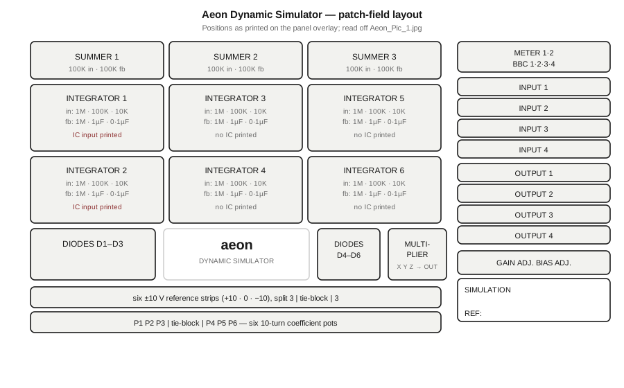
Figure 1 — The machine’s complete computing complement, as established across Volumes 2 and 3. Diagram authored for this dive; see photo_credits.txt.
7.1 About this Volume
This volume closes the series with three things: a comparison placing the Aeon among the other machines in this hub, an examination of why a machine of this kind existed at all in the late 1980s, and — the substantive deliverable — a consolidated inference ledger listing every claim in this series that rests on reasoning rather than on direct observation, with the basis and confidence for each.
The ledger exists because of how this series had to be written. With no manual, no schematic and no specification, a great deal of Volumes 4 through 6 is careful reading rather than reporting. Distributing those inferences across six volumes and marking each in passing is necessary but not sufficient; gathering them in one place is what allows a future reader with better sources to check the whole series efficiently, and to overturn the parts that deserve it.
7.2 Where the Machine Sits
Table 1 — Where the Machine Sits
| Heathkit EC-1 | EAI PACE TR-10 | GE EF-140 | Aeon Dynamic Simulator | |
|---|---|---|---|---|
| Date | 1959 | in production by about 1960 | 1961 | assembled 1988 or later |
| Technology | vacuum tube | transistor | passive; no operational amplifiers | integrated-circuit operational amplifiers |
| Amplifier elements | 9 | 10–20 | none | 9 (3 summers + 6 integrators) |
| Signal range | ±60 V | ±10 V | — | ±10 V |
| Reconfiguration | plug-in R and C elements | swap a plug-in module | — | fixed; patch position selects gain |
| Initial conditions | 3 IC supplies | on the integrator networks | — | 2 patchable, on integrators 1 and 2 only |
| Repetitive operation | yes, 0·1–15 Hz | yes, 20–500 ms | — | none |
| Readout | 50-0-50 µA centre-zero meter | null meter, 0·1 % | earphone null | centre-zero meter, class 1·5, plus an LCD display |
| Host interface | oscilloscope jacks | recorder outputs | — | 4 in, 4 out, 4 BBC channels |
| Documentation held | full manual set and schematic | brochure and specification | 1961 manual | three photographs |
Two rows repay attention.
The amplifier count. The Aeon offers nine amplifier elements — the same number as the Heathkit EC-1 of nearly thirty years earlier. Nothing about the intervening three decades of electronics increased how many amplifiers a teaching machine needed, because the constraint was never the cost of amplifiers; it was the number of elements a student can usefully patch and keep track of. What the decades changed is everything else: the EC-1’s nine amplifiers were nine vacuum tubes drawing a hundred watts and swinging ±60 V, while the Aeon’s nine are small integrated circuits on a board the size of a book.
The documentation row is the one that shaped this series, and it runs the opposite way to every other row in the table. The oldest machine here is the best documented.
7.3 Why an Analogue Computer in 1988?
This is the question the machine’s date forces, and it deserves a direct answer rather than an evasion.
By 1988 the case for analogue computation as a computing technology was long over. General-purpose digital machines had displaced it for serious work through the 1970s, and the displacement was total: better accuracy, storable programs, printable results, and no scaling problem. The BBC Microcomputer this machine was apparently built to talk to could itself integrate a differential equation numerically, to more figures than the Aeon can deliver, without a patch cord.
So the machine was not built to compute. It was built to show, and three properties of an analogue computer survive the arrival of a cheaper digital one:
The solution is continuous and simultaneous. Every variable in the problem exists at every instant as a voltage, and all of them evolve together. There is no timestep, no integration scheme, and no question of numerical stability. What the machine exhibits is not an approximation to the differential equation’s behaviour; it is a physical system obeying the same equation.
The parameters are knobs. Changing the damping ratio is turning P2 and watching the shape of the response change as the hand moves. That connection between a parameter and a behaviour is the thing the machine teaches, and it survives any amount of digital progress — it is a different cognitive experience from editing a constant and re-running.
The failure modes are instructive. Scaling a problem so that every variable uses its range without overflowing is not busywork; it obliges the student to know, in advance and in physical units, roughly how large each quantity will get. The overload lamp of Vol 6 is the enforcement mechanism, and what it enforces is understanding the problem before solving it.
Against that, the machine’s own design concedes what had changed. It has no repetitive mode and no display of its own worth reading precisely; instead it has four channels wired for a host computer. The Aeon is an analogue computer that expects a digital machine to take its results away, which is a very late-period design and an honest one. It is a teaching instrument for the analogue method, built in an era that had already settled on digital answers, and it does not pretend otherwise.
7.4 What Survived, and Why
The most durable observation this series can offer has nothing to do with electronics.
Everything this machine’s maker wrote down on paper is gone — the manual, the schematic, the specification, the price list, the catalogue, the company’s name in any traceable form. What survived is precisely and only what was physically attached to the hardware:
- the patch-field legend, which draws every computing element as a circuit with its component values (Vol 2, Vol 3);
- the
RESISTOR VALUEStable silkscreened on the board, which serves as a bill of materials for the part it sits on (Vol 4); - the markings on the devices themselves, which is the entire basis for dating the machine (Vol 1).
These three things carried enough to reconstruct the machine’s complement, its arithmetic, its modes, its semiconductor complement and its approximate date. A machine documented conventionally, with all of that in a manual and none of it on the hardware, would have left nothing recoverable at all.
That is worth stating as a general point, because it is the reason this series exists in the form it does. Documentation attached to the thing it describes cannot be separated from it, cannot go out of date, and cannot be thrown away without throwing away the object.
7.5 The Inference Ledger
Every claim in this series that goes beyond direct observation, in one place. “Observed” claims — the element counts, the printed component values, the device markings, the resistor table — are not listed, because they are read directly off the photographs and are not inferences.
7.5.1 Well-supported inferences
Table 2 — Well-supported inferences
| Claim | Basis | Where |
|---|---|---|
The TL071CP is the computing amplifier | One per computing group, beside the film capacitor the panel identifies as the integrating capacitor; JFET input is the correct choice for an integrator | Vol 4 |
The LM393P provides overload detection | A comparator is not a computing element; one sits in each group beside an LED, and the panel draws a lamp inside every amplifier | Vol 3, Vol 4 |
The DG211CJ switches perform mode control | A quad analogue switch is the device the RESET/HOLD/RUN function requires; two packages give eight switched paths | Vol 4, Vol 6 |
| The red discs on the panel are overload lamps | Follows from the comparator-per-amplifier finding above | Vol 3, Vol 6 |
| The machine is of British manufacture | Four independent conventions converge: 7K5/9K1 resistor notation, the raised middle dot in 0·1uF, the meter’s 1·5 class marking, and BBC labelling | Vol 1 |
BBC denotes the BBC Microcomputer | That host’s analogue port has exactly four channels, matching BBC 1–4; it was the standard British school computer at this date | Vol 2 |
| Assembly no earlier than 1988 | Date codes on three independent device families — LM393P 8805, TL072CP 8723, DG211CJ T8730/T8736 | Vol 1 |
7.5.2 Moderately supported inferences
Table 3 — Moderately supported inferences
| Claim | Basis | Why it is held loosely |
|---|---|---|
| Assembly no earlier than mid-1989 | One LM393N reading M8930 | A single device, read from a photograph at an angle; a maker’s logo can be mistaken for part of a date code |
DS in DS6001/B abbreviates “Dynamic Simulator” | The board prefix matches the product name on the panel | A plausible reading of an abbreviation, nothing more |
| The multiplier is an XY/Z multiplier-divider | X, Y, Z is the pin convention of period multiplier ICs, in which the third terminal enables division and square-rooting | The panel draws the block as a black box; no multiplier device was identified inside |
| The absence of a repetitive mode reflects reliance on the host | The machine has no rate control but does have four host channels | An argument from an absence together with a presence |
GAIN ADJ. and BIAS ADJ. act on the readout chain | Their names are the conventional zero-and-span pair, and they are the only adjustments brought to the front panel | Reading two labels and their placement; the multiplier and reference are also candidates |
7.5.3 Weakly supported inferences
Table 4 — Weakly supported inferences
| Claim | Basis | Status |
|---|---|---|
| The LCD display is a patchable digital voltmeter | Adjacency to the METER 1/METER 2 jacks, and the complementary-instrument argument of Vol 6 | The display is unlit in every photograph and no legend describes it |
The TL072CP packages serve reference, metering and interface duties | Their location on the lower board, away from the repeated computing groups | Location only |
7.5.4 Unresolved — both readings given, neither adopted
Table 5 — Unresolved — both readings given, neither adopted
| Question | The two readings |
|---|---|
Why only integrators 1 and 2 have an IC input | (a) A deliberate economy: a second-order problem needs exactly two initial conditions, and those two are the leftmost vertical pair. (b) The circuitry exists on all six but is brought to the panel on only two |
| How many boards the machine has | (a) A two-board stack photographed at two lift angles, with DS6002/B’s upper region obscured in one view. (b) A third, intermediate board carrying the amplifier groups, whose designation is never legible |
7.5.5 Unknown — no reading offered
- The manufacturer’s identity.
- The machine’s model number, production quantity, price and market.
- The identity and function of the 14-pin device reading
LSL 1409/3C1-69C. - The machine’s power source and supply rails.
- The function of the additional unlabelled diode inside the multiplier block.
- The potentiometers’ track resistance, and therefore all loading errors.
- Every performance figure: accuracy, bandwidth, drift, offset, slew rate, reference stability, and the tolerance of every resistor and capacitor. None is printed anywhere on the machine and none is held. This series quotes no performance number for the Aeon, because there is none to quote.
7.5.6 Derived results
These are not inferences about the machine but consequences of its printed values, obtained by ordinary operational-amplifier theory. The arithmetic is certain; what is uncertain is how closely real components follow it, which the unstated tolerances make unquantifiable.
Table 6 — Derived results
| Result | Where |
|---|---|
| The integrator gain matrix: 1, 10, 100 and 1000 s⁻¹ | Vol 5 |
| The summer relation eₒ = −(e₁ + e₂) | Vol 3, Vol 5 |
| Resistor feedback converts an integrator to a summer of gain −1, −10 or −100 | Vol 3, Vol 5 |
| The second-order patch, and the finding that the obvious three-inversion loop fails | Vol 5 |
| The pot settings P1 = (ωn/k)² and P2 = 2ζωn/k, and the constraint ωn ≤ k | Vol 5 |
7.6 What Would Settle the Open Questions
In descending order of how much each would resolve:
- A manual or teaching booklet. Would settle the IC asymmetry, the digital display, the
BBCinterface arrangement, the front-panel adjustments, every performance figure, and almost certainly the manufacturer’s identity. This is the single document worth looking for. - A schematic. Would settle everything in Vol 4’s closing list — the amplifier circuit, the mode switching, the initial-condition arrangement, what the trimmers trim, the reference circuit, the supply rails and the unidentified device.
- A second surviving machine. Would confirm whether the IC asymmetry is a design feature or particular to this example, and would supply the lower enclosure and rear that the three photographs do not show.
- Any commercial record — a catalogue page, an advertisement in a British educational-supply or electronics periodical of about 1988–1992, a price list, or a school inventory. Would identify the maker, the model number and the market.
- The lower enclosure of this machine, photographed. Would settle the power source, which is the most easily answered of the open questions and requires nothing but turning the machine over.
Searches for the manufacturer across general web sources and Wikimedia Commons, described in Vol 1 and recorded in photo_credits.txt, returned nothing corresponding to this machine. The absence of a trace is itself weak evidence that the maker was small, or local to the British educational-supply trade, or traded under a name that the wordmark does not spell in a searchable way.
7.7 Closing
The Aeon Dynamic Simulator is a late and slightly improbable object: a general-purpose electronic analogue computer built at the end of the 1980s, for a British classroom, to be patched by hand and read by a BBC Micro. It offers nine amplifier elements, six coefficient potentiometers, six diodes and a multiplier, all at ±10 V, with three modes and no repetitive operation. Its arithmetic is recoverable in full. Its manufacturer is unknown.
That combination — complete functional transparency and total commercial anonymity — is the consequence of a single design decision, made by someone whose name has not survived either: to print the machine’s documentation onto the machine. The paperwork went the way of the company. The panel is still bolted to the front, and it still says exactly what each element does.
Comments (0)