Aeon Dynamic Simulator · Volume 1
Aeon Dynamic Simulator — Volume 1 — Overview & the documentary record
What the machine is, when it was built, and the unusual shape of its evidence — three photographs, no paper, and a front panel that turns out to be its own manual
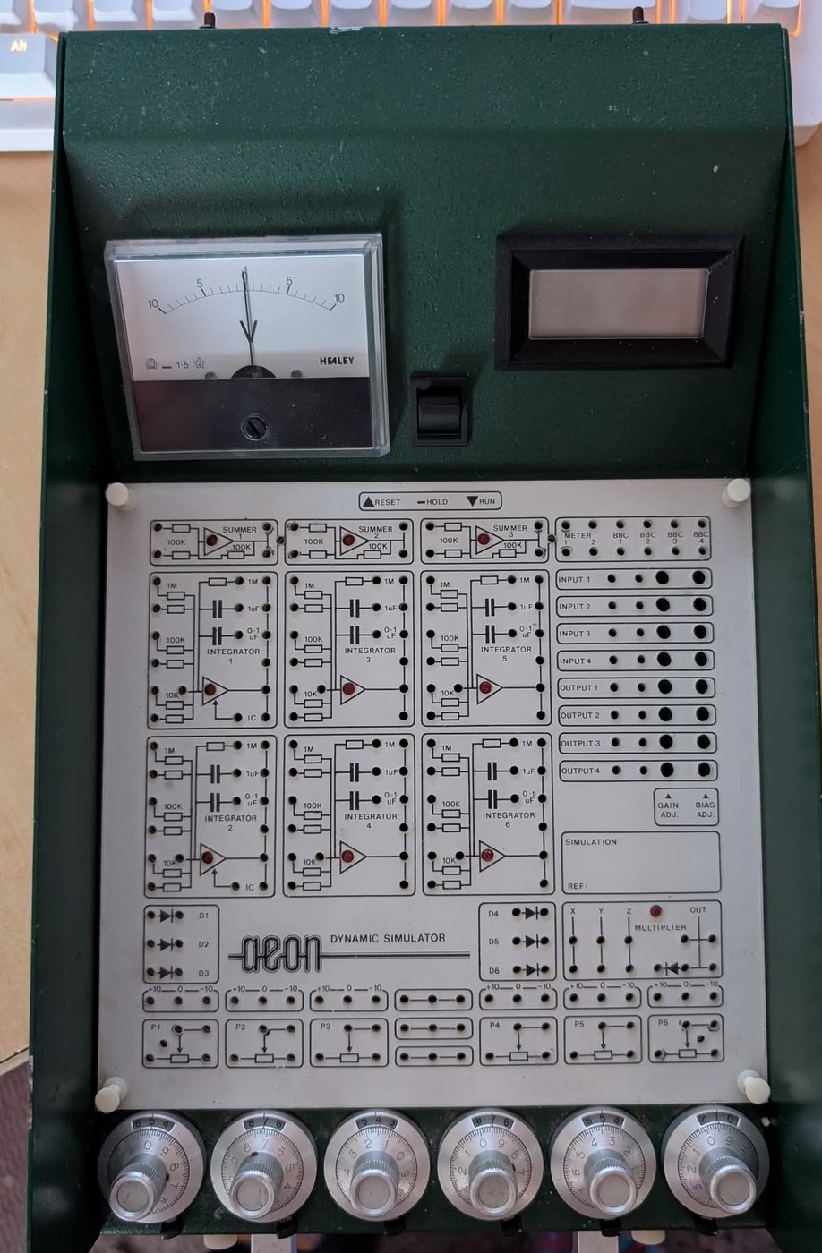
Figure 1 — The complete machine. The upper bezel carries an analogue centre-zero meter, a mode toggle and a digital panel meter; the white overlay below it is the patch field, on which every computing element is drawn as its own circuit diagram; the six knurled dials along the front edge are ten-turn coefficient potentiometers. Crop of a locally held photograph; see photo_credits.txt.
1.1 About This Volume
This volume establishes what the Aeon Dynamic Simulator is, what evidence for it survives, and how that evidence shapes everything in Volumes 2 through 7.
The shape of the record here is unusual, and it is stated first because it changes how the rest of the series should be read. For most machines in this hub the difficulty is the opposite of this one’s. The Heathkit EC-1 series rests on an assembly manual, an operating manual and a full schematic; the EAI PACE TR-10 series rests on a sales brochure and a procurement specification with no schematic at all. For the Aeon there is no paper whatsoever — no manual, no schematic, no brochure, no specification, no catalogue entry, no price list, and no trace of the manufacturer in any searchable public source.
What there is instead is the machine itself, photographed three times: once closed, and twice opened. And because whoever designed this machine chose to silkscreen each computing element’s own circuit diagram onto the patch field beside its jacks, those photographs carry more hard functional information than a sales brochure would have. The component values, the element counts, the feedback options, the mode legend and the reference voltages are all printed on the machine, in the machine’s own hand.
That is the spine of this series: the panel is the manual. Where the panel is silent — and it is silent about several important things — this series says so rather than filling the gap.
1.1.1 Depth-Index: The Seven-Volume Series
Table 1 — Depth-Index: The Seven-Volume Series
| Vol | Title | Primary content |
|---|---|---|
| 1 | Overview & the documentary record (this volume) | What the machine is, dating from device marks, the evidence and its limits, the specification quick-table, what is not known |
| 2 | The console and the patch field | Physical form, the legend-as-schematic convention, the geometry of the field, the bezel instruments, the host-computer column |
| 3 | The computing elements | Element-by-element catalogue: summers, integrators, coefficient pots, diodes, the multiplier, the reference strips, the tie blocks |
| 4 | Inside the case | The board stack, the semiconductor complement read off the photographs, the trimmer banks, the letter-coded resistor system, date codes |
| 5 | Programming and scaling | The ±10 V machine unit, summer and integrator arithmetic derived from the printed values, the gain matrix, a worked second-order program |
| 6 | Operating the machine | RESET/HOLD/RUN, the initial-condition asymmetry, readout, overload indication, and a reconstructed calibration sequence |
| 7 | Context and the open questions | Where this machine sits among teaching analogue computers, the inference ledger, and what would need to be found |
Note — Cross-references appear as “see Vol N”. Each volume is self-contained; this one assumes no other volume has been read.
1.2 What the Machine Is
1.2.1 A Solid-State Teaching Analogue Computer
The Aeon Dynamic Simulator is a self-contained, solid-state, general-purpose electronic analogue computer in a sloped-front desk enclosure, programmed by patching between jacks on a printed field, and operated by a three-position mode lever.
Its computing complement, counted directly from the panel legend, is nine amplifier-based elements: three summers and six integrators. To these are added six ten-turn coefficient potentiometers, six patchable diodes, one multiplier block, six fixed reference strips and two tie blocks. The signal range is ±10 V, established by the reference strips, which are each printed “+10 — 0 — −10”, and corroborated by the panel meter, whose scale is a centre-zero 10–5–0–5–10.
Three characteristics separate it from the vintage machines elsewhere in this hub:
- It is late. The semiconductors inside it carry date codes clustering in 1987 to 1989 (see Dating the Machine, below). This is not a machine from analogue computing’s era of dominance. It was built a decade and a half after general-purpose analogue computation had been displaced by digital machines for serious work.
- It is a teaching instrument by construction, not by price. Every computing element is drawn as a schematic on the panel next to its own jacks. A machine intended for a working engineer does not need that; a machine intended to teach what an integrator is does. The write-on box marked “SIMULATION / REF:” makes the same point — it exists so that a patched problem can be labelled and left set up for the next class.
- It expects a host computer. A column of jacks along the right of the field is labelled
INPUT 1–INPUT 4,OUTPUT 1–OUTPUT 4,METER 1–2andBBC 1–4. The reading of “BBC” is discussed below and in Vol 2; on any reading, this machine was designed to be wired to something else that digitised its results.
1.2.2 The Name
The wordmark on the panel is the lowercase word aeon, set in a distinctive geometric outline script, followed in plain capitals by DYNAMIC SIMULATOR.

Figure 2 — The wordmark, at the foot of the patch field. No model number, serial number, manufacturer address or country of origin appears anywhere on the exterior of the machine as photographed. Crop of a locally held photograph.
Two cautions about the name. First, “Dynamic Simulator” is here a product name, not a model number — nothing photographed carries a model or serial designation. The only type numbers visible anywhere on the machine are the two printed-circuit board numbers, DS6001/B and DS6002/B, and those identify boards rather than the product. “DS” plausibly abbreviates “Dynamic Simulator”, but that is a reading of an abbreviation, not a documented fact.
Second, “aeon” could not be identified as a manufacturer. Searches for the wordmark in combination with analogue computing, educational electronics and teaching equipment returned nothing corresponding to this machine, and a Wikimedia Commons search returned no photograph of it under any phrasing. No company, catalogue, advertisement or surviving sibling machine has been located. The maker of this machine is, on the evidence held here, simply unknown.
1.2.3 What the Machine Does, in One Paragraph
A variable in the problem is represented by a voltage between −10 V and +10 V. An amplifier with a resistor in its feedback path adds and inverts voltages; the same kind of amplifier with a capacitor in its feedback path integrates one with respect to time. A ten-turn potentiometer multiplies a voltage by a constant between zero and one. Patch these together in the pattern of a differential equation, move the lever from RESET to RUN, and the machine’s voltages will evolve exactly as the equation’s variables do — continuously, in parallel, and in real time. The answer is not calculated step by step; it is exhibited by a circuit obeying the same mathematics as the system under study. Vol 5 develops this properly and works an example on this machine’s actual component values.
1.3 The Documentary Record
1.3.1 What Is Held
Table 2 — What Is Held
| Source | What it is | What it carries |
|---|---|---|
| Photograph 1 | The closed machine from above, square to the panel | The complete patch-field legend: every element, its printed circuit diagram, its component values, the mode legend, the reference strips, the wordmark. The upper bezel with meter, toggle and digital display. The six ten-turn dials. |
| Photograph 2 | The machine opened, patch board displaced, component side of the computing board exposed | The semiconductor complement in the amplifier groups, trimmer types and designators, the board number DS6001/B, part of DS6002/B, connector labels, device date codes |
| Photograph 3 | The machine opened with the jack board hinged up and leaning back | The underside of the jack board; the lower board’s component side, its RESISTOR VALUES silkscreen legend, its trimmer bank VR1–VR16, test points TP1–TP4, connectors CON6 and CON7 |
All three are held locally, at full resolution, and every photographic figure in this series is a crop of one of them.
1.3.2 What Is Not Held
Stated plainly, because several volumes would read differently if any of it turned up:
- No manual of any kind — no operating manual, no teaching notes, no worked-example booklet, no maintenance manual.
- No schematic. This is the sharpest limit on the series. Vol 4 can list the devices on the boards and reason about what they are for; it cannot trace a signal through a stage, because the circuit is not held and cannot be recovered from three photographs of populated boards.
- No specification. No accuracy figure, no bandwidth, no drift figure, no offset figure, no tolerance for any resistor or capacitor. Every performance claim a manufacturer would normally make about an analogue computer is absent.
- No commercial record. No price, no catalogue, no advertisement, no production quantity, no serial range, no customer list, no date of introduction or withdrawal.
- No manufacturer identification, as set out above.
- No sibling machine. No second example has been located anywhere, in a museum collection, a private collection or a photograph.
Note — A reader arriving with an actual Aeon and a fault should treat this series as orientation and as a careful inventory, not as a service manual. Vol 4 sets out exactly which questions a schematic would answer and Vol 7 lists what would need to be found.
1.4 The Panel Is the Manual
The design decision that makes this series possible is worth stating as an engineering choice rather than a graphic one.
On most patch-programmed analogue computers the panel carries labels — INT 1, SJ, OUT — and the operator learns from a manual what lies behind them. On the Aeon, each element is instead drawn as a small schematic, with its jacks positioned at the electrically correct points on that schematic and its component values printed beside the components they belong to.
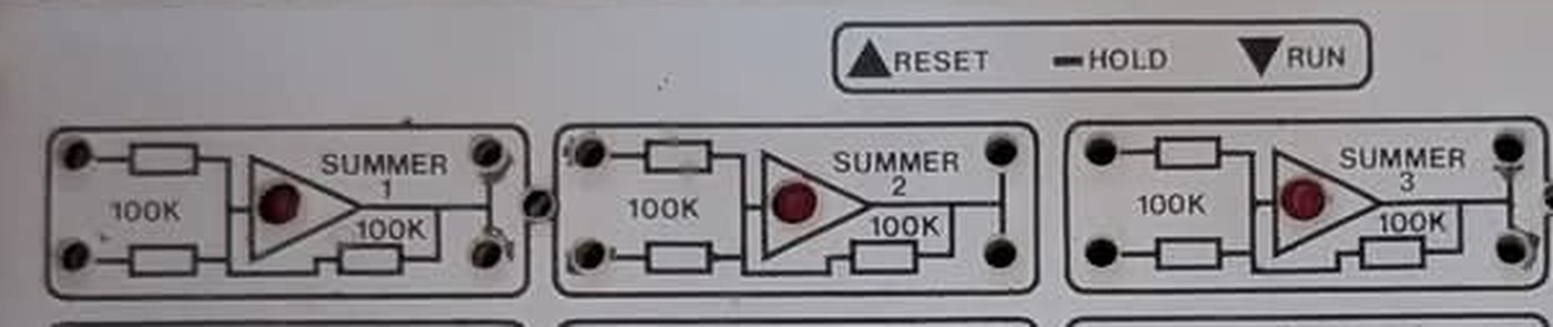
Figure 3 — The summer row. Each block is a circuit diagram, not a label: two input resistors, an amplifier symbol with an indicator lamp inside it, and a feedback resistor, all with values printed. The mode legend “▲RESET — HOLD ▼RUN” sits at the top right, beside the toggle on the bezel above. Crop of a locally held photograph.
The consequences are direct, and they run in both directions.
For the operator, the machine cannot become separated from its own documentation. Anyone who can read a circuit diagram can determine, without any manual, that summer 1 has two inputs of equal weight, that its feedback resistor is the same value as its input resistors and therefore that its gain is −1 on each input, and exactly which hole to put the patch cord in to get that. This is a genuine teaching virtue: the thing being taught is printed on the thing doing the teaching.
For this series, the same property means the machine’s functional specification survived even though every scrap of its paperwork did not. The element counts, the resistor and capacitor values, the number of reference strips, the initial-condition arrangement and the mode scheme are all recoverable at full confidence from one photograph, because the designer put them there.
What the panel does not carry is equally important and is listed in What Is Not Known, below. A printed legend states topology and component values. It says nothing about tolerance, drift, bandwidth, or what the machine’s answers are worth.
1.5 Dating the Machine
No date appears on the machine. Four lines of evidence from the interior photographs bracket it, and all four point the same way.
Table 3 — Dating the Machine
| Evidence | Reading | Indication |
|---|---|---|
LM393P comparators, marked 8805BR | Date code 1988, week 05 | Not before early 1988 |
TL072CP op-amps, marked 8723XA | Date code 1987, week 23 | Not before mid-1987 |
DG211CJ analogue switches, marked T8730 and T8736 | Date codes 1987, weeks 30 and 36 | Not before late 1987 |
One LM393N, marked M8930 | Read as date code 1989, week 30 | Not before mid-1989, if the reading is correct |
The defensible statement is therefore: the machine was assembled no earlier than 1988, and probably no earlier than the second half of 1989. The last row carries the least weight, because it is a single device read from a photograph at an angle and a manufacturer’s logo can be mistaken for part of a date code; but three independent device types agreeing on 1987–88 is solid, and nothing in the machine suggests earlier manufacture.
A further indication of origin, rather than date, is worth recording as the inference it is. The resistor values silkscreened inside use the British engineering convention in which the multiplier replaces the decimal point — 7K5, 9K1 — the capacitor legend on the panel reads 0·1uF with a raised middle dot, the meter’s accuracy class is printed 1·5 in the same style, and the host-computer jacks are labelled BBC. In a machine of this date those four things together read as British manufacture, for the British education market, where the BBC Microcomputer was the standard school computer. This is a convergence of conventions, not a documented origin, and it is flagged again in the inference ledger in Vol 7.
1.6 The Machine’s Numbers
Every row below is sourced to the physical feature it was read from. Nothing in this table is inferred, and nothing has been supplied from general knowledge of similar machines.
Table 4 — The Machine's Numbers
| Parameter | Value | Read from |
|---|---|---|
| Signal range | ±10 V | reference strips printed “+10 — 0 — −10”; meter scale |
| Summers | 3 | panel legend, SUMMER 1–3 |
| Summer inputs | 2 per summer | panel legend |
| Summer input resistors | 100 kΩ | panel legend |
| Summer feedback resistor | 100 kΩ | panel legend |
| Integrators | 6 | panel legend, INTEGRATOR 1–6 |
| Integrator input resistors | 1 MΩ, 100 kΩ, 10 kΩ — two of each, six per integrator | panel legend |
| Integrator feedback options | 1 MΩ resistor, 1 µF capacitor, 0·1 µF capacitor | panel legend |
| Integrators with a printed IC input | 2 of 6 — integrators 1 and 2 only | panel legend |
| Coefficient potentiometers | 6, P1–P6, ten-turn counting dials | panel legend and front edge |
| Diodes | 6, D1–D6 | panel legend |
| Multiplier | 1, inputs X, Y, Z, one OUT | panel legend |
| Reference strips | 6, each +10 / 0 / −10 | panel legend |
| Tie blocks | 2, three paralleled jacks each | panel legend |
| Modes | RESET / HOLD / RUN, three-position lever | panel legend and bezel toggle |
| Analogue meter | centre-zero, ±10, accuracy class 1·5, marked HEALEY | meter dial |
| Digital display | one LCD numeric panel meter, unlit in the photographs | bezel |
| Front-panel adjustments | GAIN ADJ., BIAS ADJ. | panel legend |
| Host interface jacks | INPUT 1–4, OUTPUT 1–4, METER 1–2, BBC 1–4 | panel legend |
| Board designations | DS6001/B (jack board), DS6002/B (lower board) | board silkscreen |
The single most consequential line in that table is the one in bold. Only two of the six integrators have a printed initial-condition input. Every integrator is otherwise identically drawn. Nothing on the panel explains the asymmetry, no manual is held to justify it, and its practical effect on what can be programmed is treated in Vol 5 and Vol 6.
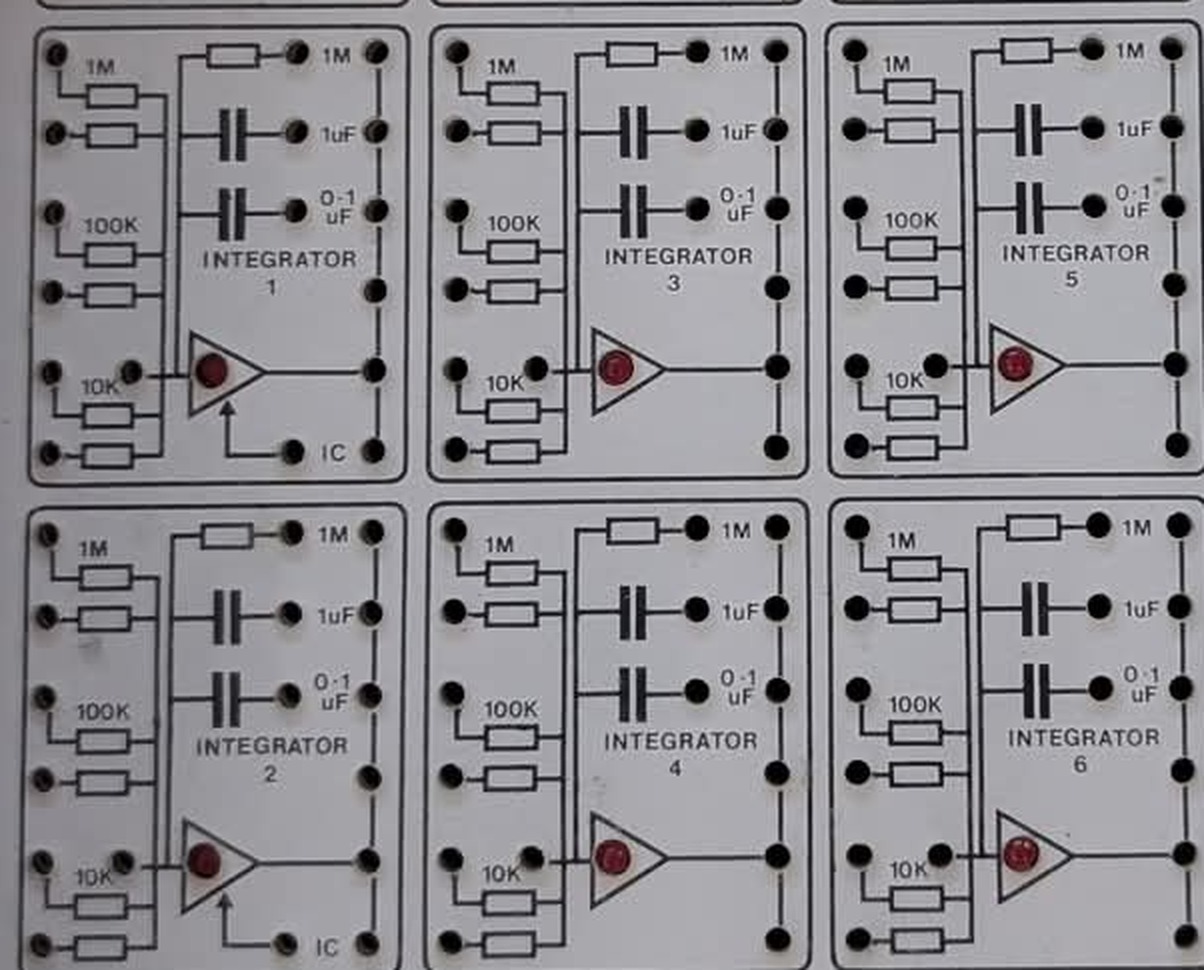
Figure 4 — The six integrators. Integrators 1 and 2, at the left of each row, carry an arrow into the amplifier and the label IC; integrators 3 through 6 do not. Every other feature of the six blocks is identical. Crop of a locally held photograph.
1.7 What Is Not Known
Set out plainly, so that no later volume has to imply otherwise:
- The manufacturer. Unknown. “aeon” is a wordmark that could not be traced.
- The date of design, introduction, or withdrawal. Only the assembly bracket above is supported.
- The price, production quantity and market. Entirely unknown.
- The circuit. The devices are legible; the topology is not. Vol 4 states what each device class is for and labels every functional claim as the inference it is.
- Every performance figure. Accuracy, bandwidth, drift, offset, amplifier slew rate, potentiometer resolution, reference stability, capacitor tolerance — none is printed anywhere and none is held. This series quotes no performance number for this machine, because there is none to quote.
- The function of the digital display. It is unlit in all three photographs, and no legend describes it. Whether it reads a selected patch point, a reference voltage or elapsed time cannot be determined.
- The meaning of
BBC. The reading adopted here — the BBC Microcomputer, the standard British school computer of the period, whose analogue port has exactly four channels to matchBBC 1–4— is the most economical explanation of a four-way group of jacks so labelled on a British teaching instrument of this date. It is not confirmed by anything held. - Why only two integrators have an IC input. Discussed in Vol 6; not resolved.
- The identity of one 14-pin device on the lower left of the computing board, whose marking is legible in the photograph but corresponds to no part identified here. See Vol 4.
1.8 Why This Machine Is Worth a Series
It is an artefact of a specific and short-lived idea. By the late 1980s no one was doing production engineering on an analogue computer. What survived, briefly, was the argument that an analogue computer is the clearest possible way to teach what a differential equation does — that watching a damping ratio change as a knob turns conveys something a printed solution does not. This machine is that argument built in hardware, a decade after the commercial case for analogue computation had gone, and wired to a BBC Micro so the results could be captured digitally. It documents a transitional moment rather than a mature technology.
Its documentation strategy is the interesting engineering decision. The choice to print each element’s schematic on the patch field rather than label it is what allowed this series to be written at all. That is a durable lesson with a sharp edge to it: the documentation that survived is the documentation that was physically attached to the thing it described. Everything kept on paper is gone.
It is the limiting case for how this hub handles evidence. The Heathkit EC-1 has a full manual set; the TR-10 has sales literature and a specification that contradict each other; the Aeon has three photographs. Working carefully from the thinnest possible record — saying precisely what is legible, what is derived, and what is simply unknown — is a discipline worth demonstrating on the machine that demands the most of it.
1.9 What Comes Next
Vol 2 opens the console: the physical form, the bezel instruments, the geometry of the patch field, and the legend-as-schematic convention treated as a design decision with consequences. Vol 3 catalogues every computing element in turn, with the values printed beside each. Vol 4 goes inside the case to the boards, the semiconductor complement and the letter-coded resistor system, and marks the boundary where a schematic would be required. Readers who want to use the machine rather than understand its construction should go to Vol 5, which derives the machine’s arithmetic from the printed component values and works a second-order problem onto it, and then Vol 6 for modes, readout and calibration. Vol 7 places the machine among its contemporaries and sets out, in one table, every inference this series has made and the confidence attaching to each.
Comments (0)